
Non-polarized receiving electrode structure

A technology of receiving electrodes and electrodes, which is applied in the field of mine detection instruments, can solve problems such as inaccurate receiving potential signals, and achieve the effects of improving measurement accuracy, improving sealing performance, and facilitating disassembly and maintenance

Active Publication Date: 2021-05-25
BC P INC CHINA NAT PETROLEUM CORP +1
View PDF8 Cites 1 Cited by
  • Summary
  • Abstract
  • Description
  • Claims
  • Application Information

AI Technical Summary

Problems solved by technology

[0003] Aiming at the technical problems existing in the prior art, the present invention provides a non-polarized receiving electrode structure to solve the technical problem that the existing receiving electrodes are prone to generate polarization potentials, resulting in inaccurate received potential signals collected

Method used


Image

  • Non-polarized receiving electrode structure
  • Non-polarized receiving electrode structure
  • Non-polarized receiving electrode structure

Examples


Embodiment

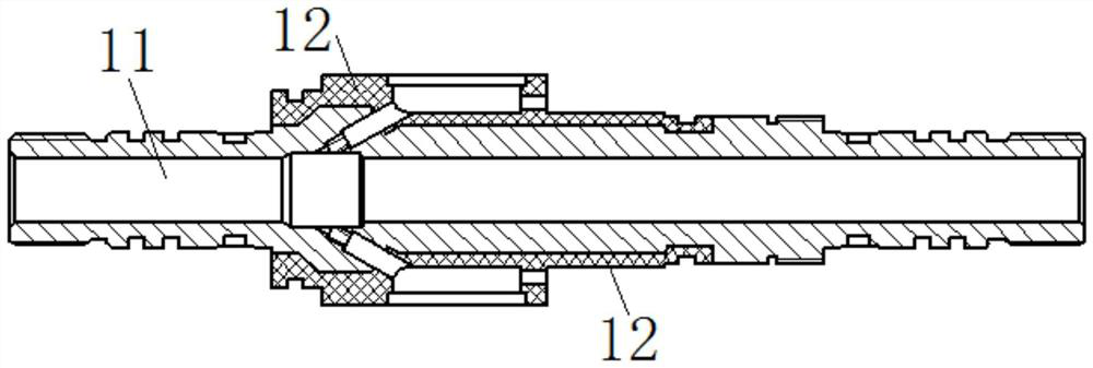
[0047] as attached Figure 1-8 As shown, this embodiment provides a non-polarized receiving electrode structure, including an electrode shaft 11, a glass fiber reinforced plastic layer 12, two pressure-bearing sealing plugs 2, two protective covers 3, silicone grease 4, two terminal posts 5, Receiving electrode 6, bushing 7, insulating sleeve 8 and support sleeve 9; FRP layer 12 is tightly sleeved on the outside of electrode shaft 11; FRP layer 12 is formed by winding FRP material on the surface of electrode shaft 11; both sides of the surface of FRP layer 12 The wire sealing grooves are symmetrically arranged respectively, and a bushing fixing position is arranged on one side of the wire sealing groove; the bushing 7 is fixedly sleeved in the bushing fixing position on the outside of the glass fiber reinforced plastic layer 12, and the receiving electrode 6 is fixedly threaded through the bushing 7 outside, and the receiving electrode 6 is a non-polarized electrode; in the pr...


PUM


Abstract

The invention discloses a non-polarized receiving electrode structure which comprises a base body electrode, a lining is fixedly arranged on the base body electrode in a sleeving mode, and a receiving electrode is fixedly arranged on the outer side of the lining in a penetrating and sleeving mode. An insulating sleeve fixedly sleeves the base body electrode and is arranged at the end parts of the receiving electrode and the lining. An inclined hole is formed in the receiving electrode and is far away from one end of the insulating sleeve; the pressure-bearing sealing plug is fixedly installed in the inclined hole, the binding post is arranged in the lining, one end of the binding post is connected with the receiving electrode, and the other end of the binding post is connected with the pressure-bearing sealing plug through a connecting wire. The receiving electrode adopts a non-polarized electrode. According to the invention, the bushing is arranged on the substrate electrode, the receiving electrode sleeves the bushing, and the insulating sleeve is used for fixing the receiving electrode and the bushing, so that isolation between the receiving electrode and surrounding metal is ensured; and the receiving electrode adopts the non-polarized electrode, so that the influence of an environmental solution is avoided, the accuracy of acquired data is high, the measurement precision is greatly improved, and disassembly and replacement are convenient.

Description

technical field [0001] The invention belongs to the technical field of mineral deposit detection instruments, and in particular relates to a non-polarization receiving electrode structure. Background technique [0002] In the field of oil and metal deposit exploration, electrical instruments are usually used to analyze and determine the material content in the formation; when the electric instrument transmits current through the formation, the current signal is collected by the receiving electrode, and the material content contained in the formation is determined through analysis; in the past The receiving electrode of the electric method instrument is generally made of stainless steel or lead skin; the disadvantage is that the stainless steel or lead skin itself will generate a polarization potential in the solution, resulting in inaccurate received potential signals collected. Contents of the invention [0003] Aiming at the technical problems existing in the prior art, ...

Claims


Application Information

Patent Timeline
IPC IPC(8): G01V3/02
CPCG01V3/02Y02A90/30
Inventor 杨海贺飞郭庆明李晓孙七零程刚范晓文王伟
Owner BC P INC CHINA NAT PETROLEUM CORP
Learn More