Highway drainage device

A drainage device and road technology, applied in the field of road administration, can solve problems such as increased driving hazards, obstructed sightlines, waste of materials for electric drainage equipment, etc.

Active Publication Date: 2021-05-25
广西旺达建工有限公司
View PDF11 Cites 3 Cited by
  • Summary
  • Abstract
  • Description
  • Claims
  • Application Information

AI Technical Summary

Problems solved by technology

[0002] Road transportation is the most flexible and convenient mode of transportation in my country at the present stage. With the development of road construction, the impact of road drainage on roads has become increasingly prominent; road accumulation of water will reduce the friction between high-speed vehicles and the ground, thus This leads to the phenomenon that the braking distance is long, which is a potential safety hazard and is not conducive to ensuring the safe driving of the vehicle; in addition, when the vehicle passes through the waterlogged section at high speed, the waterlogged area where the tires of the vehicle pass through will form water mist, which will be sprayed on the subsequent On the vehicle, the sight of the driver of the following vehicle will be blocked, and the driver will not be able to drive normally, which will increase the danger of driving. Therefore, when building a road, it is generally necessary to effectively design its drainage facilities
[0003] Existing highway drainage devices generally only rely on pipelines, and floor drains are buried at the ground openings of the pipelines. However, when the rainfall is too large, the floor drains cannot meet the excessive drainage volume, resulting in the need to use electric drainage equipment for auxiliary drainage. However, electricity Drainage equipment needs a large power for auxiliary drainage when draining water. After working for a long time, it will greatly waste power resources. At the same time, the production of electric drainage equipment itself will also greatly waste materials, resulting in waste and loss of resources. Environmental protection greatly reduced sex

Method used


Image

  • Highway drainage device
  • Highway drainage device
  • Highway drainage device

Examples


Embodiment Construction

[0024]Next, the technical solutions in the embodiments of the present invention will be apparent from the embodiment of the present invention, and it is clearly described, and it is understood that the described embodiments are merely embodiments of the present invention, not all of the embodiments. Based on the embodiments of the present invention, there are all other embodiments obtained without making creative labor without making creative labor premises.

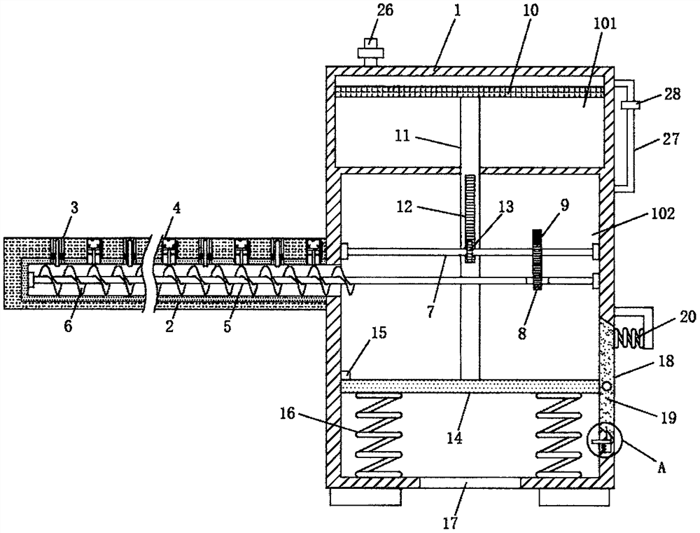
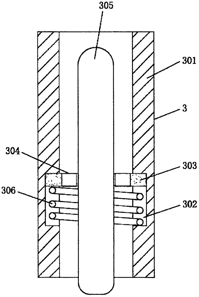
[0025]SeeFigure 1-4One embodiment of the present invention is: a highway drainage device, including the device box 1, and the inside of the apparatus tank 1 is provided with a first cavity 101 and a second cavity 102. On one side of the device box 1 in communication with a water pipe 2. The water pipe 2 is disposed in sequentially equal intervals, and the top of the water pipe 2 is located at the intermediate position of each of the two sets of info mechanism 3, and the inner portion of the water pipe 2 is connected to the second...


PUM


Abstract

The invention discloses a highway drainage device. The highway drainage device comprises a device box, wherein a first cavity and a second cavity are formed in the device box; one side of the device box communicates with a water pipe; water inlet mechanisms are sequentially arranged at the top of the water pipe at equal intervals; and a water absorbing mechanism is arranged at the top of the water pipe and is positioned between each two water inlet mechanisms. A third piston can be driven to descend by gravity of rainwater, by descending of the third piston, the various mechanisms are matched with parts, any power equipment is not required to assist in drainage, the use amount of the power equipment is reduced effectively, power resources are saved, meanwhile, the production of a power equipment manufacturer is also reduced, consumption of materials is reduced, resources are saved, the environment is protected, meanwhile, water drained from the device box can effectively wash the inside of a groove, the groove can be cleaned without extra cleaning equipment, and the resources are utilized effectively.

Description

Technical field[0001]The present invention relates to the roadshoot field, specifically a highway drainage device.Background technique[0002]Highway transportation is the most flexible transportation mode of China's current stage. With the development of road construction, road drainage has become increasingly highlighted; the stream of highways will make the friction between the high-speed vehicle and the ground becomes small, thus The phenomenon of braking distance, there is a safety hazard, which is not conducive to ensuring the safe driving of the vehicle; in addition, when the vehicle passes through the water segment at high speed, the water-pressed water area of ​​the vehicle forms a water mist, spray in subsequent On the vehicle, thereby causing the subsequent vehicle driver's line of sight to blocked, not normal driving, increasing the dangers of driving, so in the construction of the road, it is generally necessary to effectively design their drainage facilities.[0003]The ex...

Claims


Application Information

Patent Timeline
Patent Type & Authority Applications(China)
IPC IPC(8): E03F1/00E03B3/02
CPCE03F1/00E03B3/02Y02A20/108
Inventor 李彦伟王辉辉苏鹏郭超马晋
Owner 广西旺达建工有限公司
Why Eureka
Try Eureka