Manufacturing process of cooling type grain-grain viscose fiber and product

A production process and fiber technology, which is applied in the field of composite fiber production technology, can solve the problems of increasing the manufacturing difficulty, increasing the manufacturing cost, and the effect is not obvious, and achieving the effect of reducing the manufacturing difficulty, being easy to operate, and not difficult to operate.

Pending Publication Date: 2021-05-25
WUHAN RED GOLDEN LEAF NEW MATERIAL TECH CO LTD
View PDF6 Cites 0 Cited by
  • Summary
  • Abstract
  • Description
  • Claims
  • Application Information

AI Technical Summary

Problems solved by technology

[0003] The existing cooling design is mostly a cylindrical structure, including the outer wrapping layer and the cooling structure filled inside. The commonly used cooling structure includes multiple fiber bundles arranged side by side, or a folded structure of sheet materials. Although these cooling structures A certain cooling effect can be obtained, but the effect is not obvious. In addition, when these cooling structures are produced, due to their complex structures, the manufacturing difficulty is increased and the production cost is increased.

Method used


Image

  • Manufacturing process of cooling type grain-grain viscose fiber and product
  • Manufacturing process of cooling type grain-grain viscose fiber and product
  • Manufacturing process of cooling type grain-grain viscose fiber and product

Examples


Embodiment 1

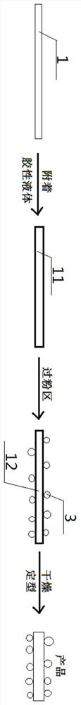
[0055] see figure 1 — Figure 7 , a kind of manufacturing process of cooling formula granular viscose fiber, comprises the following steps:

[0056] The first step: first use the fiber filaments to make the core yarn 1, and then attach a colloidal liquid to the outer surface of the core yarn 1 to obtain the viscous core yarn 11; the colloidal liquid is an adhesive, acetic acid spinning solution or viscose Spinning solution; the fiber silk is viscose fiber, cotton fiber, hemp fiber, chitin fiber, alginate fiber, chitosan fiber, polyvinyl alcohol fiber, polycaprolactone fiber, polyglycolic acid ester fiber any one or any combination of

[0057] The second step: first pass the viscous core yarn 11 through the powder area 2, and a plurality of PLA powder particles 3 are arranged in the powder area 2. When passing through, the PLA powder particles 3 are combined with the outer surface of the viscous core yarn 11. , to obtain powdered yarn 12; the binder is any one of pectin, pol...

Embodiment 2

[0061] Basic content is the same as embodiment 1, the difference is:

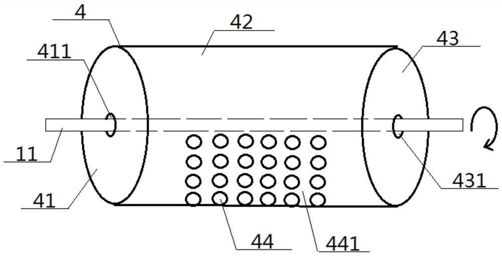
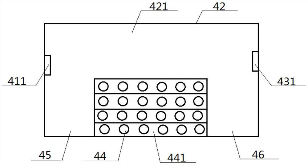
[0062] Said passing the viscous core yarn 11 from the powder area 2 refers to passing the viscous core yarn 11 axially through the powder sticking cylinder 4, which includes a front cylinder cover 41, a middle cylinder body 42, and a rear cylinder arranged in sequence. Cover 43, the two ends of the middle cylinder body 42 are respectively sealed and connected with the front cylinder cover 41 and the rear cylinder cover 43. The front cylinder cover 41 and the rear cylinder cover 43 are respectively provided with a yarn inlet hole 411 and a yarn outlet hole 431. The inside of the cylinder body 42 is a middle cylinder chamber 421, and the side circumference of the middle cylinder body 42 is provided with a plurality of powder inlets 44 communicating with the middle cylinder chamber 421. A front empty area 45 and a rear empty area 46 are respectively clamped between the cylinder covers 43;

[0063] When the vi...

Embodiment 3

[0065] Basic content is the same as embodiment 1, the difference is:

[0066] The arrangement area 441 is set lower than the viscous core yarn 11 ; the arrangement structure of the powder inlets 44 is: there are at least two rows, and each row includes at least two powder inlets 44 . When the viscous core yarn 11 passes through the powder sticking cylinder 4, the viscous core yarn 11 rotates while moving in the axial direction.


PUM


Abstract

Disclosed is a manufacturing process of cooling type particle viscose fiber. The manufacturing process comprises the steps that firstly, cellosilk is used for manufacturing a core yarn, then colloidal liquid is attached to the outer surface of the core yarn to obtain viscous core yarn, then the viscous core yarn passes through a powder area, a plurality of PLA powder particles are arranged in the powder area, when passing, the PLA powder particles are combined with the outer surface of the viscous core yarn to obtain yarn with powder, and drying and shaping are conducted on the yarn with powder to obtain the cooling type particle viscose fiber as a product. The cellosilk is any one or any combination of viscose, cotton fiber, fibrilia, chitin fiber, alginic acid fiber, chitosan fiber, polyvinyl alcohol fiber, polycaprolactone fiber and polyglycolate fiber. According to the design, the manufacturing difficulty is relatively low, and the cooling effect of the product is relatively high.

Description

technical field [0001] The invention relates to a manufacturing process of a composite fiber, which belongs to the field of flue gas cooling, and in particular to a manufacturing process and a product of a cooling type viscose fiber. Background technique [0002] In the existing tobacco products, whether it is a cigarette or a heat-not-burn tobacco, it is necessary to set a cooling design inside the structure. When it is applied, the smoke generated by the cooling design is used to cool down the temperature, so as to avoid the excessive temperature. The smoke burns the user's mouth, and secondly, it can reduce the production of harmful substances, making it healthier and more environmentally friendly. [0003] The existing cooling design is mostly a cylindrical structure, including the outer wrapping layer and the cooling structure filled inside. The commonly used cooling structure includes multiple fiber bundles arranged side by side, or a folded structure of sheet material...

Claims


Application Information

Patent Timeline
Patent Type & Authority Applications(China)
IPC IPC(8): D02G3/40
CPCD02G3/40D02G3/402D02G3/404D10B2201/24D10B2201/02D10B2201/01D10B2331/04
Inventor 王蕾胡睿青
Owner WUHAN RED GOLDEN LEAF NEW MATERIAL TECH CO LTD
Why Eureka
Try Eureka