
Compressor cooling machine for oil refining and chemical engineering

A technology for oil refining, chemical industry, and compressors, which is applied in the direction of furnace cooling, crucible furnace, furnace, etc., and can solve the problems of hidden dangers of compressed oil liquid tube bursting, interference with thermal expansion and conduction of oil refining, and easy gyration of control deviations.

Inactive Publication Date: 2021-05-18
曾丽琼
View PDF0 Cites 0 Cited by
  • Summary
  • Abstract
  • Description
  • Claims
  • Application Information

AI Technical Summary

Problems solved by technology

[0004] Aiming at the deficiencies in the prior art, the purpose of the present invention is to provide a compressor cooler for oil refinery and chemical industry, to solve the problem that the centrifugal compression of the oil refinery and chemical compressor combined with the spiral propulsion of the cold seam pipeline easily causes frosting around the pressure and refrigeration operation. The phenomenon of sudden drop and contraction occurs when the temperature drops, which interferes with the thermal expansion and conduction capacity of oil refining, and the cold contraction can easily compress the oil rapidly, causing the hidden danger of tube explosion, and the control deviation of the cooling degree and evaporation efficiency is easy to increase, and the pipeline is compressed and cooled alternately It leads to the reduction of subsequent mechanical linkage and conduction, and the problem of inhibiting the operation of oil refining

Method used


Image

  • Compressor cooling machine for oil refining and chemical engineering
  • Compressor cooling machine for oil refining and chemical engineering
  • Compressor cooling machine for oil refining and chemical engineering

Examples


Embodiment 1

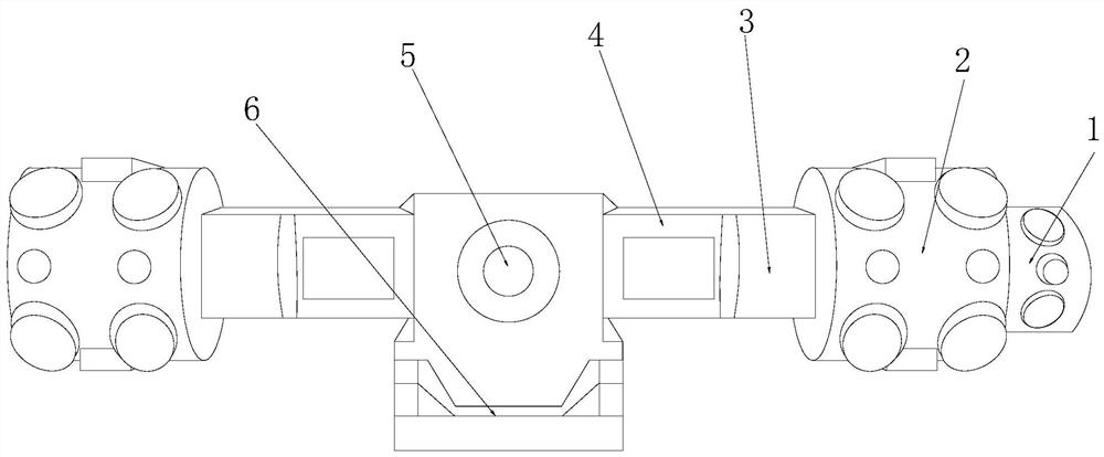
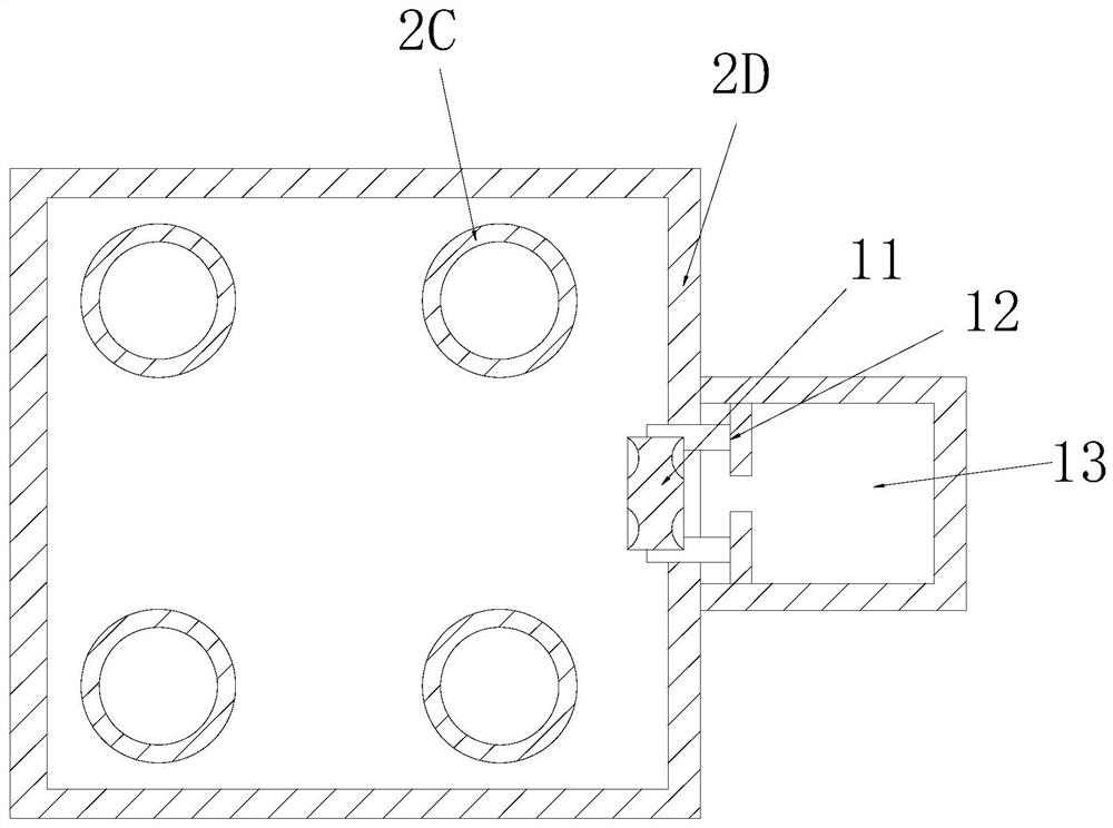
[0035] see Figure 1-Figure 8 , the present invention provides a compressor cooler for oil refining and chemical industry, its structure includes: sleeve groove 1, cooling compression drum 2, deflector column plate groove 3, frame groove body 4, rotating shaft disk 5, box seat groove 6, The cooling compression drum 2 is nested on the left side of the sleeve groove 1 and the axes are collinear. The cooling compression drum 2 is fastened together with the deflector column plate groove 3, and the deflector column plate groove 3 It is integrated with the frame tank 4 and is on the same vertical plane. The rotating shaft disk 5 is installed on the top of the box seat groove 6 and is perpendicular to each other. There are two frame tanks 4 and they are respectively inserted in On the left and right sides of the rotating shaft disk 5, the cooling compression drum 2 is provided with a bladder backing plate shaft frame 2A, a condensation pipe folding groove 2B, a through-hole ring fram...

Embodiment 2

[0043] see Figure 1-Figure 8 , the present invention provides a compressor cooler for refining and chemical industry, other aspects are the same as in Embodiment 1, the difference is:

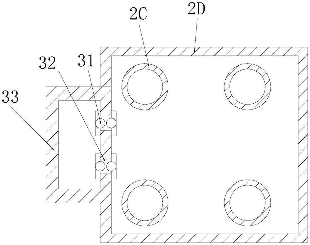
[0044] see image 3 , the guide column plate groove 3 is composed of a button wheel 31, an I-shaped fastener 32, and a column plate shell groove 33. The button wheel 31 and the I-shaped fastener 32 are fastened together and are on the same vertical plane, The I-shaped fastener 32 is installed on the right side of the column plate shell groove 33 , and the I-shaped fastener 32 is fastened to the column plate shell groove 33 to form the locking operation effect of the shell.

[0045] see Figure 6 , the button wheel 31 is made up of the fan plate shaft wheel groove 311, the arc lobe plate 312, and the arc rail bar 313. The fan plate shaft wheel groove 311 and the arc lobe plate 312 adopt clearance fit, and the arc lobe plate 312 and the arc lobe plate The rail rods 313 are nested together and...


PUM


Abstract

The invention discloses a compressor cooling machine for oil refining and chemical engineering. The machine structurally comprises a sleeve groove, a cooling compression rotary drum, a flow guide column plate groove, a frame groove body, a rotating shaft disc and a box seat groove. According to the machine, cooperation of the cooling compression rotary drum and the flow guide column plate groove is applied, a split through hole is formed in a through hole petal cap groove of a condenser pipe folding groove and an inclined condenser pipe to regulate and control the petal pressure convolution operation effect, the softness of convolution compression heat value refrigeration and cooling of a whole folding groove pipeline and a bag base plate shaft frame is improved, and effective unloading operation of a turning and pressing winding is guaranteed when a subsequent column plate shell groove is connected with a folding groove pipeline. The relief amplitude increase of rotation of a convex bag base plate and a trapezoid column plate is ensured, linkage and the conduction amount of a whole single-screw propulsion rack are guaranteed, air channels are continuously and transversely conducted in a segmented manner, the oil refining heat value balance operation effect is guaranteed, and the cooling operation tightness of follow-up hot air dissipation is improved.

Description

technical field [0001] The invention relates to a compressor cooler for oil refining and chemical industry, which belongs to the field of oil refining. Background technique [0002] The comprehensive function of the compressor and cooler used in the refining and chemical plant is to heat the furnace to assist oil refining to prevent the explosion of the tank, and the subsequent superimposed use of cooling efficiency is higher and the temperature balance adjustment is more perfect, increasing the increase in oil refining and protection. , complete the mobility of the overall assembly line processing, the shortcomings of the current technology to be optimized are: [0003] The centrifugal compression of the compressor used in oil refining and chemical industry combined with the helical propulsion of the cold seam pipeline is likely to cause frosting around the pressure and the cooling operation of the refrigeration operation will cause a sudden drop in the temperature of the r...

Claims


Application Information

Patent Timeline
Patent Type & Authority Applications(China)
IPC IPC(8): F27B14/08F27D9/00
CPCF27B14/08F27B2014/0837F27D9/00F27D2009/0005F27M2003/13
Inventor 许春晖
Owner 曾丽琼
Learn More