
Glass coating machine and coating process thereof

A coating machine, glass technology, applied in the direction of coating, the device for coating liquid on the surface, etc., can solve the problems of splashing off the plate, trouble, easy to break and so on

Pending Publication Date: 2021-05-18
尚刘镇
View PDF4 Cites 3 Cited by
  • Summary
  • Abstract
  • Description
  • Claims
  • Application Information

AI Technical Summary

Problems solved by technology

[0003] The disadvantage of the general glass coating machine is that when the general glass coating machine is coating, the glass plate needs to be clamped to the equipment first, because the glass plate is relatively brittle and easy to be broken, so it needs to be handled with care when clamping. For the clamping workers, it is more troublesome; and the general coating method mainly adopts the method of spraying, which sprays the material body that is originally in a viscous state on the end surface of the glass plate, but because the spraying method mainly relies on pressure to rush the material body to On the plate, when the material body contacts the end of the plate, it will be subject to recoil force, which is prone to splashing and detaching from the plate, resulting in material waste, and it is also easy to cause differences in the thickness of the sprayed film layer. At the same time, generally after the film layer is sprayed , in order to make the film smooth, a trowel is used for smoothing, but when the trowel is used directly, the part of the overly thick film material will be pushed, and there is adhesion between the sprayed film materials, so the upper layer that is pushed The film material will drive the underlying film material to move, which will easily cause the sprayed film layer to break

Method used


Image

  • Glass coating machine and coating process thereof
  • Glass coating machine and coating process thereof
  • Glass coating machine and coating process thereof

Examples


Embodiment Construction

[0034] The following will clearly and completely describe the technical solutions in the embodiments of the present invention with reference to the accompanying drawings in the embodiments of the present invention. Obviously, the described embodiments are only some, not all, embodiments of the present invention. Based on the embodiments of the present invention, all other embodiments obtained by persons of ordinary skill in the art without making creative efforts belong to the protection scope of the present invention.

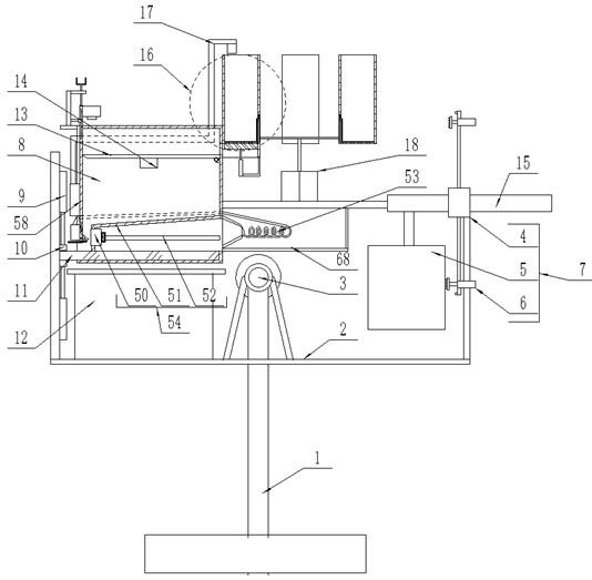
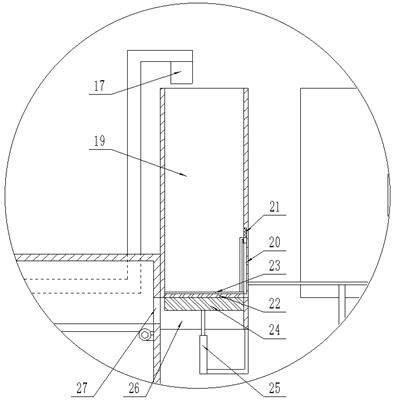
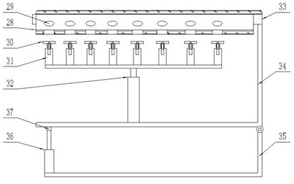
[0035] see Figure 1-11, the present invention provides a technical solution: a glass coating machine, comprising a main support frame 1, the upper end of the main support frame 1 is fixedly connected with a main motor 3, the main shaft end of the main motor 3 is horizontally forward, and the main shaft end of the main motor 3 Horizontally fixedly connected with a rotating bracket 2, the upper side of the left end of the rotating bracket 2 is symmetrically fix...


PUM


Abstract

The invention discloses a glass coating machine and a coating process thereof. The device comprises a main supporting frame; a main motor is fixedly connected to the upper end of the main supporting frame; a rotating support is horizontally and fixedly connected to the main shaft end of the main motor; main hydraulic telescopic rods are fixedly connected to the upper side of the left end of the rotating support in a vertically symmetrical mode; and a glass conduction mechanism and a coating box are arranged on the rear side of the left end of the rotating support. An auxiliary driving motor is started, so that the auxiliary driving motor drives a rotating guide plate to slowly rotate anticlockwise, and coating slurry on the rotating guide plate downwards flows to fall on a glass plate due to inclination of the rotating guide plate; a high-speed driving motor is started, and the high-speed driving motor drives a transmission disc to rotate at a high speed, so that cutters linearly distributed on a transmission belt are operated and translated rightward along with a coating box to cut off a coating slurry part higher than the lower end of a lifting side plate, and it is guaranteed that the slurry attached to the upper end surface of the glass plate is uniform in thickness.

Description

technical field [0001] The invention relates to the technical field of glass coating machines, in particular to a glass coating machine and a coating process thereof. Background technique [0002] The glass coating machine is a device used to coat the end surface of glass material. Due to the requirements of some glass material usage scenarios, it is necessary to coat the end surface to achieve other different effects; [0003] The disadvantage of the general glass coating machine is that when the general glass coating machine is coating, the glass plate needs to be clamped to the equipment first, because the glass plate is relatively brittle and easy to be broken, so it needs to be handled with care when clamping. For the clamping workers, it is more troublesome; and the general coating method mainly adopts the method of spraying, which sprays the material body that is originally in a viscous state on the end surface of the glass plate, but because the spraying method mainl...

Claims


Application Information

Patent Timeline
Patent Type & Authority Applications(China)
IPC IPC(8): B05C5/00B05C9/14B05C11/02B05C11/10B05C13/02
CPCB05C5/004B05C13/02B05C11/1005B05C11/1039B05C9/14B05C11/028
Inventor 尚刘镇
Owner 尚刘镇
Learn More