
Air foam flooding method for reducing gas channeling for underground thickened oil exploitation and air foaming agent of foam flooding for reducing gas channeling for underground thickened oil exploitation

A technology for air foam flooding and downhole heavy oil, which is applied in the fields of production of fluids, chemical instruments and methods, and earth-moving drilling, etc., can solve problems such as poor oil washing ability, reduce the occurrence of gas channeling, and improve the efficiency of control and flooding and oil washing. , the effect of good foam quality

Active Publication Date: 2021-05-14
西安石油大油气科技有限公司
View PDF12 Cites 3 Cited by
  • Summary
  • Abstract
  • Description
  • Claims
  • Application Information

AI Technical Summary

Problems solved by technology

However, there is a certain gap between the pore seepage law of air foam flooding in the experiment and the actual formation state, and further research is needed to optimize the air foam flooding technology and solve the problems of gas channeling
[0004] The selection and application of foaming agent is the key to realize air foam flooding. Reasonable selection of foaming agent can effectively improve foaming performance and foaming stability. In actual production, different types of foaming agents or surfactants are usually compounded Form a mixed system to make up for the defects in the performance of a single foaming agent or surfactant to achieve better results. However, due to the relatively high interfacial tension between the foaming agent and crude oil, it has poor performance in oil washing, so It is necessary to study and improve the performance of the foaming agent to obtain a more stable foaming agent with higher oil washing efficiency

Method used


Image

  • Air foam flooding method for reducing gas channeling for underground thickened oil exploitation and air foaming agent of foam flooding for reducing gas channeling for underground thickened oil exploitation

Examples


Embodiment 1

[0030] The downhole heavy oil development adopts the air foam flooding method to reduce gas channeling, including the following steps:

[0031] S1 preparation work: collect dynamic production data in the work area, prepare sufficient water, ensure sufficient gas source, prepare sufficient foaming agent, and install gas pressure sensor and nitrogen detector into the casing of the production well;

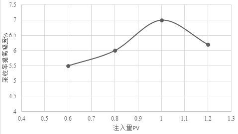
[0032]S2 Pre-injection: Advance water injection at one end of the water injection well. When the water content near the production well reaches 70%, the pre-air foam is injected. The foaming method of the pre-air foam is ground foaming. The ground mixing time is 18 minutes, the injection method is gas-liquid simultaneous injection, the gas-liquid volume ratio is 1.25:1, the injection rate is 7.5L / min, and the injection volume is 0.6PV. The nitrogen content of the production well is monitored in real time. When the mass content is 15-30%, reduce the injection rate to the minimum value...

Embodiment 2

[0038] This embodiment is basically the same as Embodiment 1, except that the water cut near the production well is different when the injection starts, so the gas-liquid volume ratio, injection rate and injection volume need to be adjusted according to the water cut.

[0039] S2 Pre-injection: Advance water injection at one end of the water injection well. When the water content near the production well reaches 75%, the pre-air foam is injected. The foaming method of the pre-air foam is ground foaming. The ground mixing time is 15 minutes, the injection method is gas-liquid simultaneous injection, the gas-liquid volume ratio is 1.35:1, the injection rate is 8L / min, and the injection volume is 1PV. The nitrogen content of the production well is monitored in real time. When the mass content of nitrogen When it is 15-30%, reduce the injection rate to the minimum value of the preset value. When the mass content of nitrogen is 30-50%, reduce the injection rate to 3.5L / min. When the...

Embodiment 3

[0044] This embodiment is basically the same as Embodiment 1, except that the water cut near the production well is different when the injection starts, so the gas-liquid volume ratio, injection rate and injection volume need to be adjusted according to the water cut.

[0045] S2 Pre-injection: Advance water injection at one end of the water injection well. When the water content near the production well reaches 80%, the pre-air foam is injected. The foaming method of the pre-air foam is ground foaming. The ground mixing time is 20 minutes, the injection method is gas-liquid simultaneous injection, the gas-liquid volume ratio is 1.45:1, the injection rate is 9L / min, and the injection volume is 1.2PV. The nitrogen content of the production well is monitored in real time. When the quality of nitrogen When the content is 15-30%, reduce the injection speed to the minimum value of the preset value. When the mass content of nitrogen is 30-50%, reduce the injection speed to 4L / min. Wh...


PUM


Abstract

The invention discloses an air foam flooding method for reducing gas channeling for underground thickened oil exploitation and a foaming agent of the foam flooding for reducing gas channeling for the underground thickened oil exploitation. The method comprises the following steps of S1, preparation work; S2, pre-injection; S3, slug injection, specifically, the slug injection are divided three groups in total, a slug combination 1 is repeated twice for 0.06PV air foam flooding and 0.04PV water flooding, a slug combination 2 is repeated for six times for 0.03PV air foam flooding and 0.03PV water flooding, and a slug combination 3 is repeated for four times for 0.05PV three-phase mixed foam flooding and 0.05PV water flooding; S4, post-injection; and S5, parameter adjustment, and the foaming agent is prepared from the following components of, in percentage by mass, 0.43%-0.46% of anionic surfactant, 0.32%-0.35% of ampholytic surfactant and the balance water. According to the air foam flooding method, the purpose of effectively reducing the gas channeling is achieved in a step-by-step injection mode, the nitrogen content is monitored in real time, the gas injection speed and the liquid injection speed are regulated and controlled, the plugging effect of air foam flooding is effectively improved on the premise that the gas channeling does not occur, and the profile control and displacement and the oil washing efficiency of the air foam flooding are greatly improved.

Description

technical field [0001] The invention relates to the technical field of air foam flooding in oil exploitation, in particular to an air foam flooding method and a foaming agent thereof for reducing gas channeling in downhole heavy oil development. Background technique [0002] As one of the very efficient tertiary oil recovery technologies, foam flooding technology has developed rapidly in recent years. After it is injected into oil-bearing formations, it can effectively improve the swept area of ​​water injection and oil washing efficiency, and reduce the surface active substances in it. The oil-water interfacial tension and the adjustment of the oil-water mobility ratio are of great significance to the prevention and control of water channeling and gas channeling. However, due to the poor fluidity of crude oil in oil production, it is difficult to achieve a good production effect by relying on the oil reservoir's own pressure production or general water injection development...

Claims


Application Information

Patent Timeline
Patent Type & Authority Applications(China)
IPC IPC(8): E21B43/16E21B43/22E21B43/20C09K8/594C09K8/588C09K8/90C09K8/584C09K8/60C09K8/94
CPCC09K8/584C09K8/588C09K8/594C09K8/602C09K8/604C09K8/905C09K8/94E21B43/16E21B43/166E21B43/20
Inventor 邢艳斌张相春张国华赵晨李昂张鑫邢志辉孟高
Owner 西安石油大油气科技有限公司
Learn More