
Mechanical multi-group rear cantilever transverse moving type parking device

A technology of parking equipment and rear cantilever, which is applied in the field of mechanical multi-group rear cantilever lateral movement parking equipment, and can solve the problem of few parking spaces

Pending Publication Date: 2021-05-14
衡水强大停车设备有限公司
View PDF0 Cites 2 Cited by
  • Summary
  • Abstract
  • Description
  • Claims
  • Application Information

AI Technical Summary

Problems solved by technology

[0003] The purpose of the present invention is to provide a mechanical multi-group rear cantilever traverse type parking equipment, aiming to solve the problem of few parking spaces in the prior art

Method used


Image

  • Mechanical multi-group rear cantilever transverse moving type parking device
  • Mechanical multi-group rear cantilever transverse moving type parking device
  • Mechanical multi-group rear cantilever transverse moving type parking device

Examples


Embodiment 1

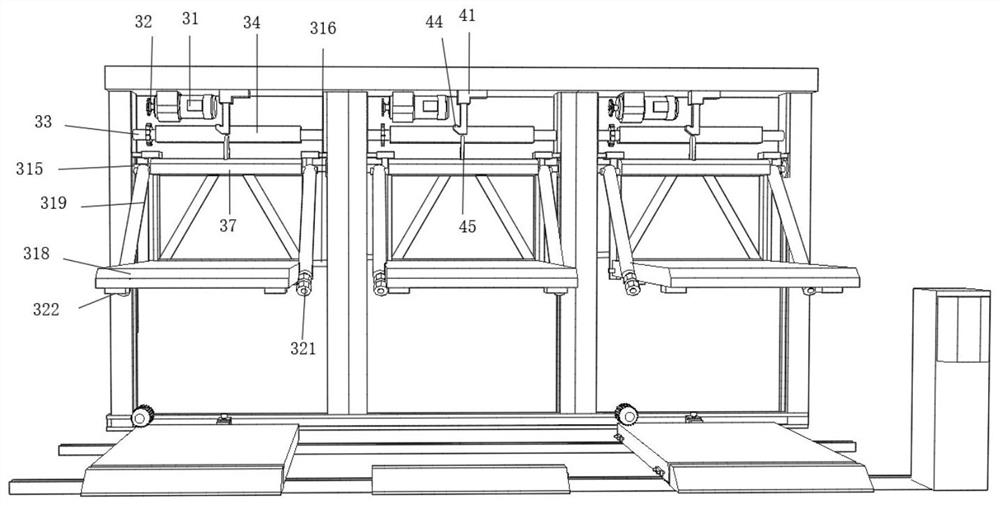
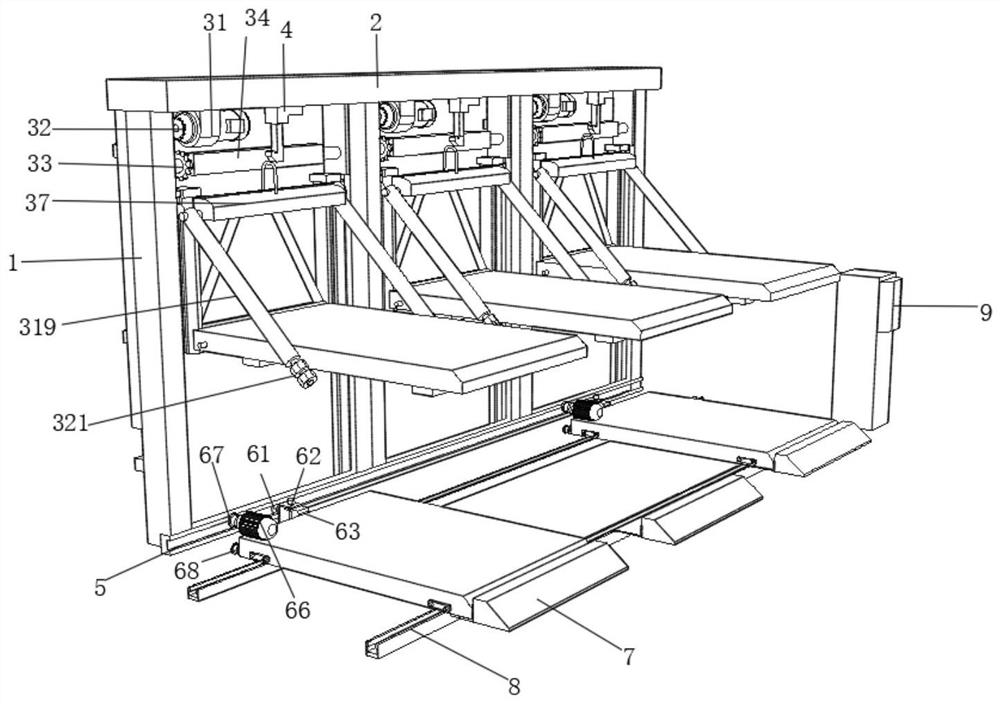
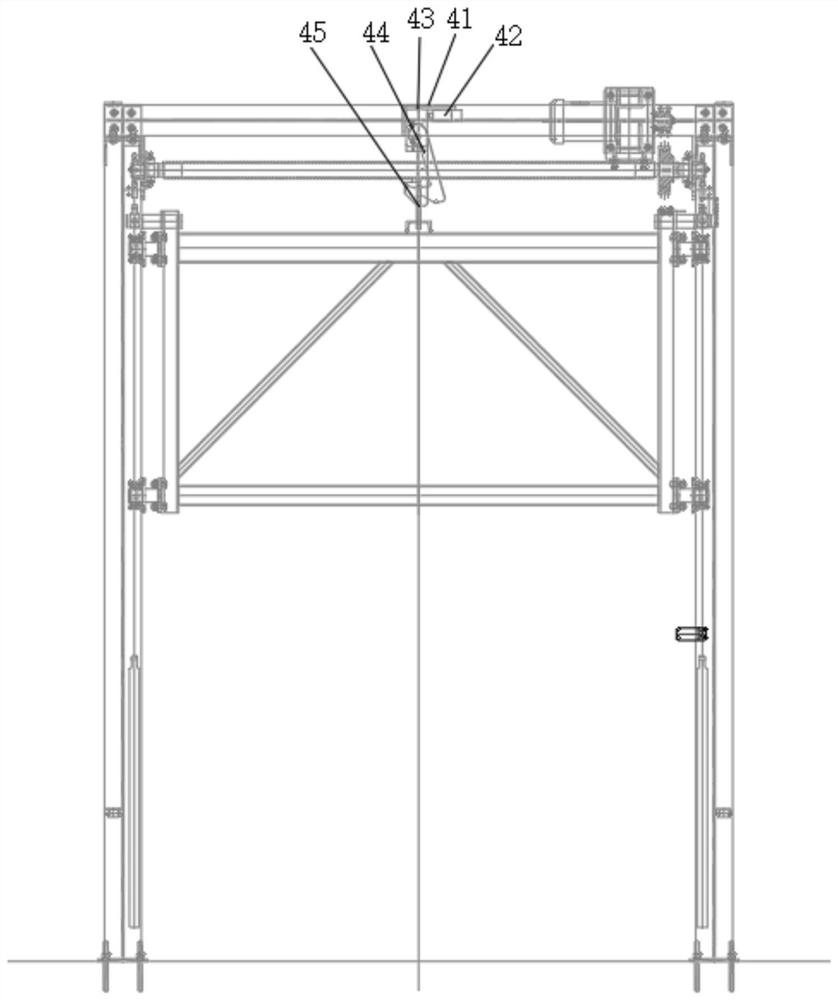
[0023] see Figure 1-6 , the present invention provides the following technical solutions: a mechanical multi-group rear cantilever traverse type parking equipment, including a support frame 1, a chute is provided on one side of the support frame 1, and an upper beam 2 is fixedly connected to the top of the support frame 1, and the upper beam 2 A lifting mechanism 3 is fixedly installed on one side of the bottom, an anti-falling device 4 is fixedly installed in the middle of the bottom end of the upper beam 2, and a guide rail 5 is fixedly connected to the bottom end of the support frame 1, and the guide rail 5 is slidingly connected to a translation device 6, and the translation device 6 One end is provided with a buffer seat 7, and the bottom end of the translation device 6 is provided with a slide rail 8, and one end of the slide rail 8 is fixedly connected with a switch panel 9.

[0024] Preferably, the lifting mechanism 3 includes a stepping motor 31 fixedly connected to ...

Embodiment 2

[0033] The difference from Embodiment 1 is that this embodiment includes a manufacturing method of the support pad:

[0034] 1) Mix 1-2 parts of carbon black, 1-3 parts of barium oxide, 5-7 parts of niobium pentoxide, 8-12 parts of erbium oxide, 5-7 parts of neodymium oxide, and 8-12 parts of hexamethyldisilazane 28-30 parts of reinforcing agent, 28-30 parts of accelerator and 28-30 parts of vulcanizing agent, 28-30 parts of ferric oxide, 28-30 parts of structural control agent, 28-30 parts of graphite powder into powder, and after sieving, pour it into a three-dimensional mixer for mixing treatment to obtain a mixed powder for subsequent use;

[0035] 2) Combine 22-26 parts of styrene-butadiene rubber, 7-11 parts of dammar resin, 11-19 parts of terpene resin, 12-22 parts of polyester resin, 28-30 parts of active agent, and 28-30 parts of tackifying resin Pour it into a container, then heat it to 150°C until the solid material is completely melted, stir well, and make a mixed...


PUM


Abstract

The invention provides a mechanical multi-group rear cantilever transverse moving type parking device. The mechanical multi-group rear cantilever transverse moving type parking device comprises a supporting frame, wherein a sliding groove is formed in one side of the supporting frame, an upper cross beam is fixedly connected to the top end of the supporting frame, a lifting mechanism is fixedly installed on one side of the bottom of the upper cross beam, an anti-falling device is fixedly installed in the middle of the bottom end of the upper cross beam, a guide rail is fixedly connected to the bottom end of the supporting frame, a translation device is slidably connected to the guide rail, a buffer seat is arranged at one end of the translation device, and a sliding rail is arranged at the bottom end of the translation device. According to the mechanical multi-group rear cantilever transverse moving type parking device, the lifting mechanism is arranged, when a vehicle is parked in a parking space of an upper table plate, the parking space is lifted, a first driving gear is driven by a stepping motor, so that the first driving gear rotates to drive a gear rotating roller to rotate, a second chain is fixedly connected with a sliding block through one end of a second driving gear, the chain has a guide effect on the chain through a limiting collision block, the other end of the chain is fixed to a lifting sliding block, so that the lifting of a lifting frame is more convenient, the parking space is saved, and the parking space is increased.

Description

technical field [0001] The invention belongs to the technical field of parking equipment, and in particular relates to a mechanical multi-group rear cantilever traverse type parking equipment. Background technique [0002] With the continuous growth of automobile consumption, the difficulty of parking in cities has become a thorny problem faced by various places. The establishment of three-dimensional parking equipment is an effective way to solve the static traffic in cities. At present, various types of parking garages have been established in large and medium-sized cities. Existing parking lots, whether they are on the ground, below, or on the top floor, occupy a large area, waste limited parking area resources, and take a long time to access cars, which is not convenient for centralized management. Scratching of vehicles is easy to happen, the customer's car enters the parking lot or leaves the parking lot and waits for a long time, the customer complains more, and the c...

Claims


Application Information

Patent Timeline
IPC IPC(8): E04H6/18E04H6/42C08L101/00C08L9/06C08L45/00C08L67/00C08L93/00C08K13/02C08K3/04C08K3/22C08K5/544C08K3/28
CPCC08K2003/2206C08K2003/221C08K2003/2213C08K2003/2272C08K2003/282C08L101/00C08L2205/035E04H6/18E04H6/42E04H6/422C08L9/06C08L45/00C08L67/00C08L93/00C08K13/02C08K3/04C08K3/22C08K5/544C08K3/28
Inventor 郝沄沄
Owner 衡水强大停车设备有限公司
Learn More