
Automatic focusing device and camera module

A technology for automatic focusing and installation space, which is applied in the direction of focusing devices, focusing devices, camera focusing devices, etc., and can solve the problems of time response efficiency degradation, time delay of automatic focusing function, limited design environment of devices, components and components, etc. To achieve the effect of improving the time response characteristics

Active Publication Date: 2021-05-11
JAHWA ELECTRONICS
View PDF13 Cites 0 Cited by
  • Summary
  • Abstract
  • Description
  • Claims
  • Application Information

AI Technical Summary

Problems solved by technology

[0009] Therefore, since the device or the actuator using the lens has a considerable length, it is difficult to optimize the basic features related to the miniaturization or slimming of the device for the mobile terminal, and the design of other devices, elements and components in the mobile terminal environment is quite limited
[0010] In addition, in the case of a device or an actuator using a lens, since the moving distance of the lens becomes longer to realize the auto focus function (AF), the time for realizing the auto focus function (AF) is delayed, so that the time response Efficiency degradation

Method used


Image

  • Automatic focusing device and camera module
  • Automatic focusing device and camera module
  • Automatic focusing device and camera module

Examples


Embodiment Construction

[0054] Hereinafter, preferred embodiments of the present disclosure will be described in detail with reference to the accompanying drawings. Before the description, it should be understood that the terms used in the specification and appended claims should not be construed as limited to the ordinary and dictionary meanings, but based on the principle of allowing the inventor to define the terms appropriately for the best interpretation, based on the same The meanings and concepts corresponding to the disclosed technical aspects are explained.

[0055] Therefore, the descriptions presented here are only preferred examples for the purpose of illustration, and are not intended to limit the scope of the present disclosure, so it should be understood that other equivalents and modifications can be made thereto without departing from the scope of the present disclosure. .

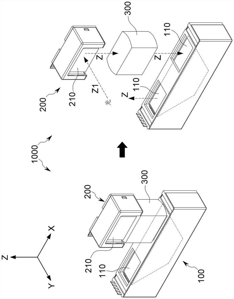
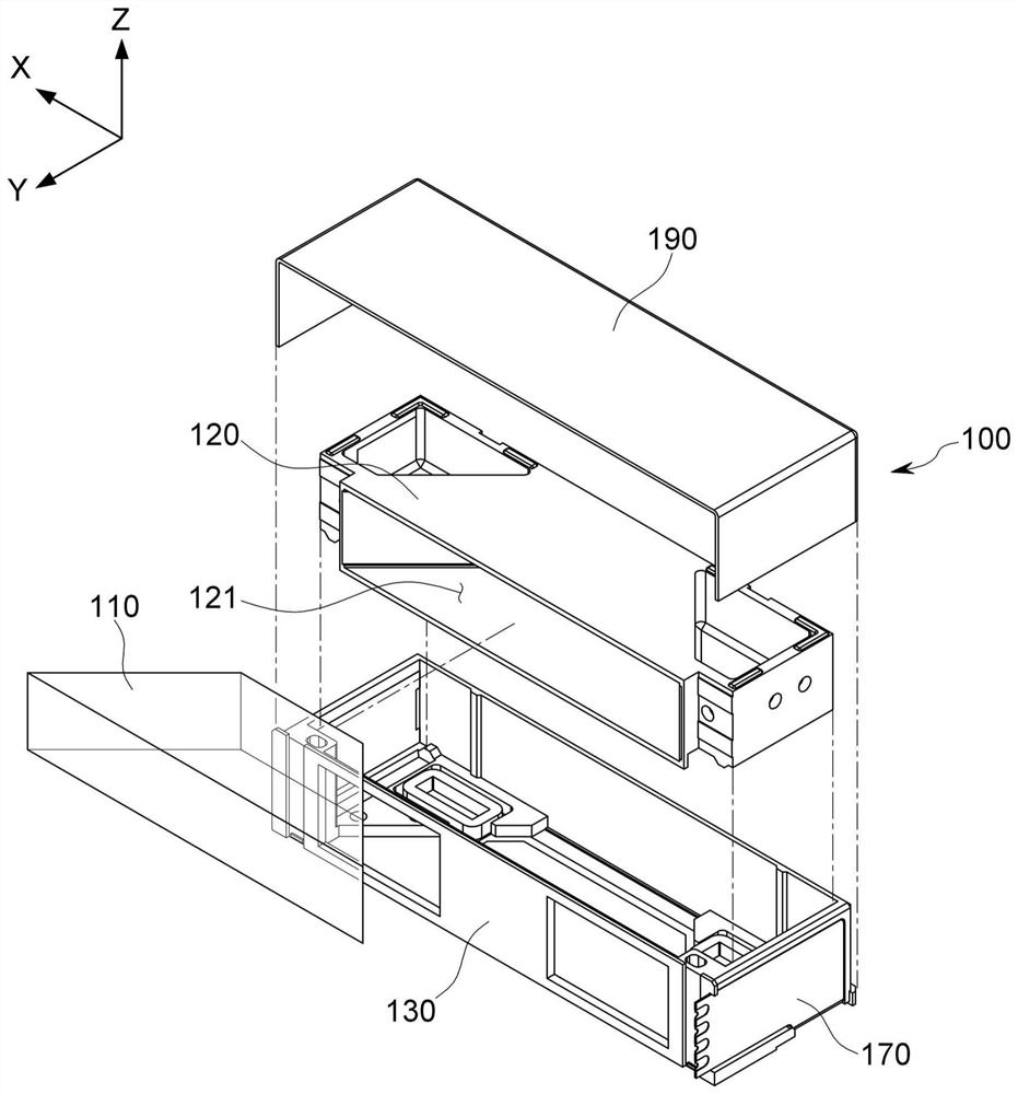
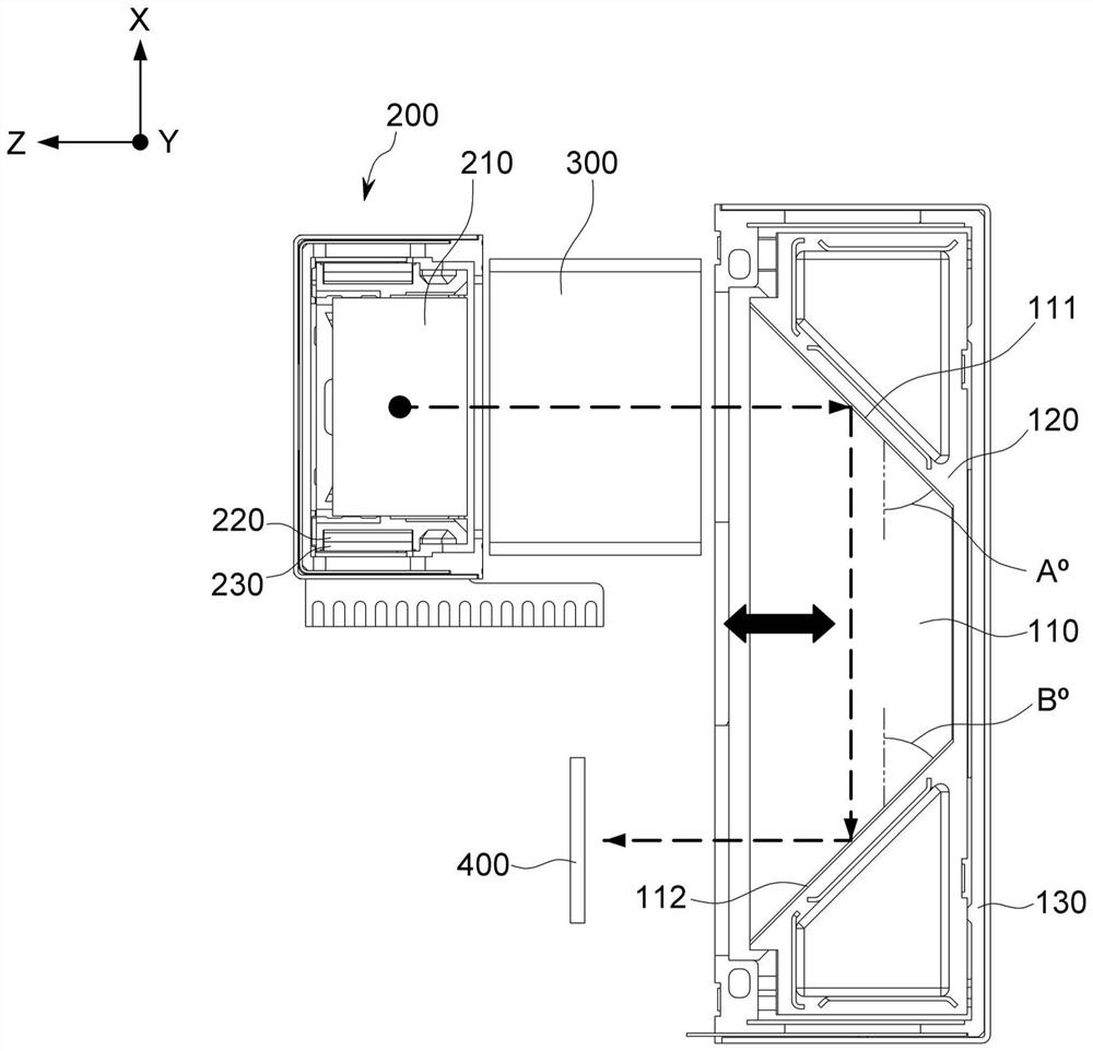
[0056] figure 1 and figure 2 is a diagram showing the overall configuration of the autofocus device 100 an...


PUM


Abstract

The invention relates to an automatic focusing device and a camera module, and the automatic focusing device comprises: a reflector, which is disposed at the rear side of a lens assembly and is configured to change the path of light passing through the lens assembly so as to enable the light to be oriented towards an image sensor; a bracket, to which the reflector is mounted, the bracket configured to linearly move in an optical axis direction; a housing configured to accommodate the carriage; and a driving unit configured to move the carriage such that a distance between the reflector and the lens assembly simultaneously changes with a distance between the reflector and the image sensor.

Description

technical field [0001] The present disclosure relates to an auto focus device and a camera module including the auto focus device, and more particularly, to an auto focus device for implementing an auto focus function by moving an optical system between a lens and an image sensor, and the like. Background technique [0002] With the development of hardware technology for image processing and the increase in user demand for image capture, functions such as autofocus (AF) and optical image stabilization (OIS) have been applied to devices such as cellular phones and smartphones. camera modules for portable terminals and stand-alone camera devices. [0003] An auto focus (AF) function (or, a function of automatically focusing) refers to generating a clear image at an image sensor (CMOS, CCD, etc.) positioned behind the lens by linearly moving a carriage having a lens in the direction of an optical axis. A function of the focal length of the subject. [0004] In addition, an Op...

Claims


Application Information

Patent Timeline
Patent Type & Authority Applications(China)
IPC IPC(8): G02B7/182G02B7/105G02B7/09G03B13/36
CPCG02B7/182G02B7/105G02B7/09G03B13/36G02B5/04G03B30/00G03B3/10G03B17/17G03B17/12H04N23/54H04N23/55
Inventor 朴铁顺李柄徹李景容延济丞姜印洙
Owner JAHWA ELECTRONICS
Learn More