Heartbeat and heart rate detection circuit
A technology for detecting circuit and heart rate, applied in the medical field, can solve the problems of large heart rate error and low accuracy
- Summary
- Abstract
- Description
- Claims
- Application Information
AI Technical Summary
Problems solved by technology
Method used
Image

Examples
Embodiment 1
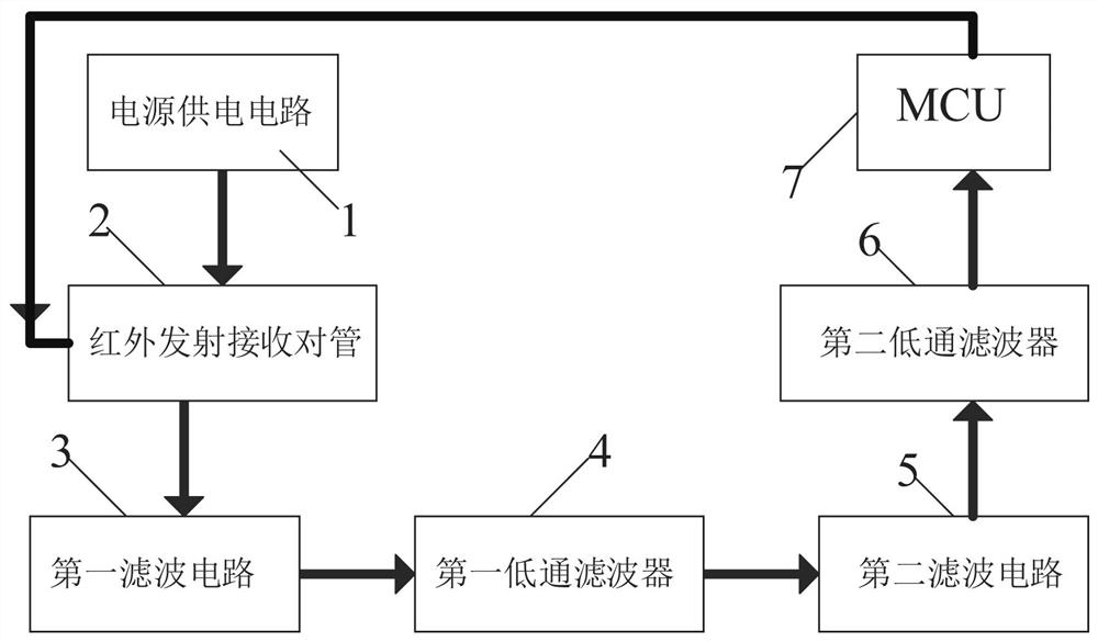
[0020] A heartbeat heart rate detection circuit, such as figure 1 As shown, it includes a power supply circuit 1, an infrared transmitting and receiving pair tube 2, a first filter circuit 3, a first low-pass filter 4, a second filter circuit 5, a second low-pass filter 6 and an MCU7. The transmitting and receiving pair tube 2 is connected to the input end of the first filter circuit 3, the output end of the first filter circuit 3 is connected to the first low-pass filter 4, and the first low-pass filter 4 is connected to the second filter circuit The input terminal of 5 is connected, and the second filter circuit 5 is connected with the second low-pass filter 6, and the second low-pass filter 6 is connected with the MCU7, and the MCU7 is connected with the infrared transmitting and receiving pair tube 2, and the The power supply circuit 1 supplies power for the infrared transmitting and receiving pair tube 2, the first filter circuit 3, the first low-pass filter 4, the second...
Embodiment 2
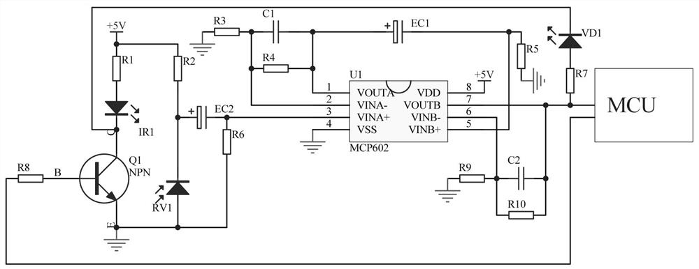
[0023] A heartbeat heart rate detection circuit, such as figure 2 As shown, the infrared transmitting and receiving pair tube 2 includes a triode Q1, an infrared transmitting tube IR1, an infrared receiving tube RV1, a resistor R1-resistor R2 and a resistor R8, the emitter of the triode Q1 is grounded, and the base of the triode Q1 A resistor R8 is connected in series, the collector of the triode Q1 is connected in series with the infrared emitting tube IR1 and the resistor R1, the other end of the resistor R1 is connected to +5V, the infrared receiving tube RV1 is connected in series with a resistor R2, and the other end of the resistor R2 is connected to +5V, the other end of the infrared receiving tube RV1 is grounded.
[0024] The first filter circuit 3 includes an operational amplifier MCP602, resistor R3-resistor R6, electrolytic capacitor EC1-electrolytic capacitor EC2 and capacitor C1, the 4 pins of the operational amplifier MCP602 are grounded, and the 8 pins of the ...
PUM
 Abstract
Description
Claims
Application Information
 - Generate Ideas
- Intellectual Property
- Life Sciences
- Materials
- Tech Scout
- Unparalleled Data Quality
- Higher Quality Content
- 60% Fewer Hallucinations
Browse by: Latest US Patents, China's latest patents, Technical Efficacy Thesaurus, Application Domain, Technology Topic, Popular Technical Reports.
© 2025 PatSnap. All rights reserved.Legal|Privacy policy|Modern Slavery Act Transparency Statement|Sitemap|About US| Contact US: help@patsnap.com