Optical cable identification method and optical cable identification device
An identification method and an identification device technology, which are applied to measuring devices, testing optical fiber/optical waveguide equipment, optical instrument testing, etc., can solve the problems of complex optical cable identification devices, high cost, and large noise, and prevent thresholds from not converging and coherent The effect of short time and widening spectrum
- Summary
- Abstract
- Description
- Claims
- Application Information
AI Technical Summary
Problems solved by technology
Method used
Image
Examples
Embodiment 1
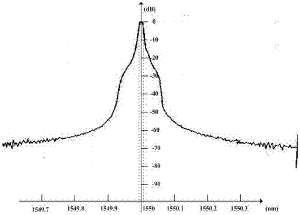
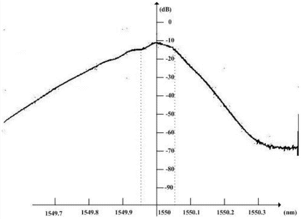
[0055] combine figure 1-2. This embodiment describes in detail the optical cable identification device of the present invention, which includes: a light source 1, a first coupler 2, a second coupler 3, a third coupler 4, a fourth coupler 5 and a detector 6, The light emitted by the light source 1 passes through the first coupler 1 and is divided into two paths, namely the first direction and the second direction. The light in the first direction passes through the second coupler 3 and then returns to the first coupler 2 to reach the light source 1. Among them, it plays the role of widening the spectrum. The widening effect is shown in Figure 2. It can be seen from the figure that the 3dB bandwidth before the spectrum widening is 0.0166nm, and the 3dB bandwidth after the spectrum widening is 0.1005nm. The light in the second direction reaches the third coupler 4 and is divided into two paths. The first direction is connected to the delayed light 8 and then reaches the fourth co...
Embodiment 2
[0058] combine image 3 , this embodiment describes the optical cable identification device of the present invention in detail. The difference between it and Embodiment 1 is that the reflection unit in the first direction of the first coupler 2 is different, and it does not include the second coupler 3, but in the first A reflector 9 is arranged on the end face of the output end of the coupler 2 in the first direction, so that the light from the light source passing through the first coupler 2 in the first direction is all reflected back into the light source 1 .
[0059] In different embodiments, a total reflection film may also be coated on the end surface of the output end of the first coupler 2 in the first direction, and the same effect as that of the reflector 9 may also be achieved.
Embodiment 3
[0061] combine Figure 4 , the present embodiment describes in detail the optical cable identification method of the present invention, which includes the following steps:
[0062] (1) Utilize the optical cable identification device of embodiment 1 or embodiment 2, obtain the signal of the optical cable feedback to be measured by interference method;
[0063] (2) Obtain the initial threshold of the current signal; assuming a set of data (m, m is a positive integer) is Signal(i), first take the absolute value of the signal to obtain AbsSignal(i), using the formula:
[0064] Signal_Threshold(i)=(Signal_Threshold(i-1)*(k-1)+AbsSignal(i)) / k (1)
[0065] Wherein, Signal_Threshold(i) is the initial threshold obtained, i is the serial number of the current signal, 1<i<m, k is a positive integer, (experimental verification, when taking k=8192, noise filtering effect and threshold convergence effect it is good);
[0066] (3) Multiply the preliminary threshold Signal_Threshold(i) of ...
PUM
 Abstract
Description
Claims
Application Information
 - Generate Ideas
- Intellectual Property
- Life Sciences
- Materials
- Tech Scout
- Unparalleled Data Quality
- Higher Quality Content
- 60% Fewer Hallucinations
Browse by: Latest US Patents, China's latest patents, Technical Efficacy Thesaurus, Application Domain, Technology Topic, Popular Technical Reports.
© 2025 PatSnap. All rights reserved.Legal|Privacy policy|Modern Slavery Act Transparency Statement|Sitemap|About US| Contact US: help@patsnap.com


