
Design and processing method of a lamp reflector

A design method and reflector technology, applied in reflectors, lighting and heating equipment, components of lighting devices, etc., can solve the problems of different bacterial inactivation rates, low energy utilization rate, uneven illumination distribution, etc. The effect of improving energy utilization, flexible method and simple processing method

Active Publication Date: 2022-07-29
师大瑞利光电科技(清远)有限公司
View PDF0 Cites 0 Cited by
  • Summary
  • Abstract
  • Description
  • Claims
  • Application Information

AI Technical Summary

Problems solved by technology

The disadvantages of these secondary light distribution designs are: on the target lighting surface, the illuminance distribution is uneven, or the energy utilization rate is not high, or the structure is relatively complicated.
In the application of indoor lighting, the uneven illuminance not only makes it more difficult to arrange the lamps, but also the different illuminance received by people at different illuminance points will damage the eyesight
In the application of UV-C sterilization, uneven illumination will cause different inactivation rates of bacteria on different parts of the target surface, which will affect the sterilization effect

Method used

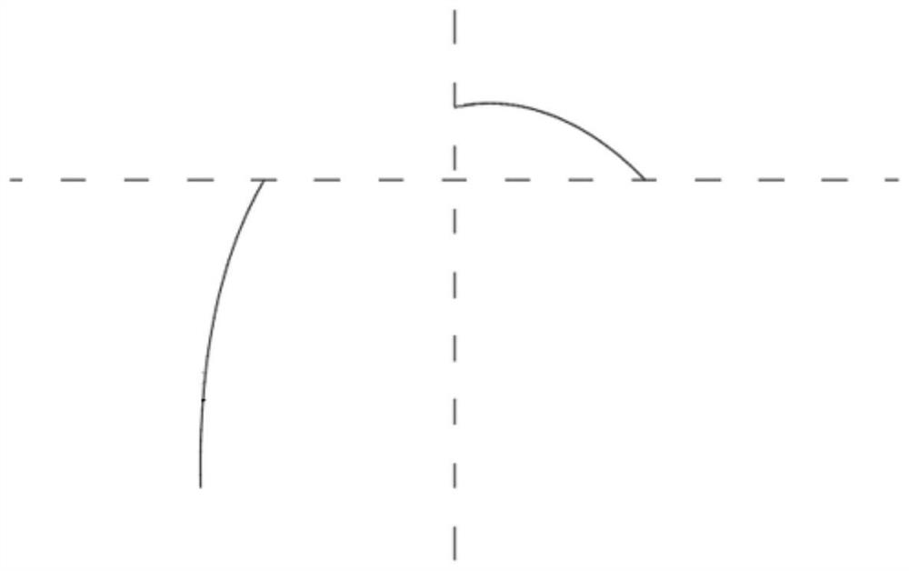
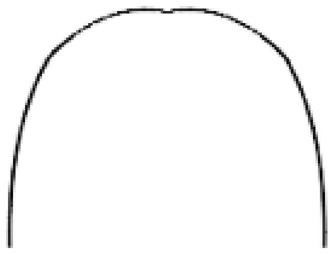

Image

  • Design and processing method of a lamp reflector
  • Design and processing method of a lamp reflector
  • Design and processing method of a lamp reflector

Examples


Embodiment

[0060] Select the UV germicidal lamp as the lamp tube described in the reflector design:

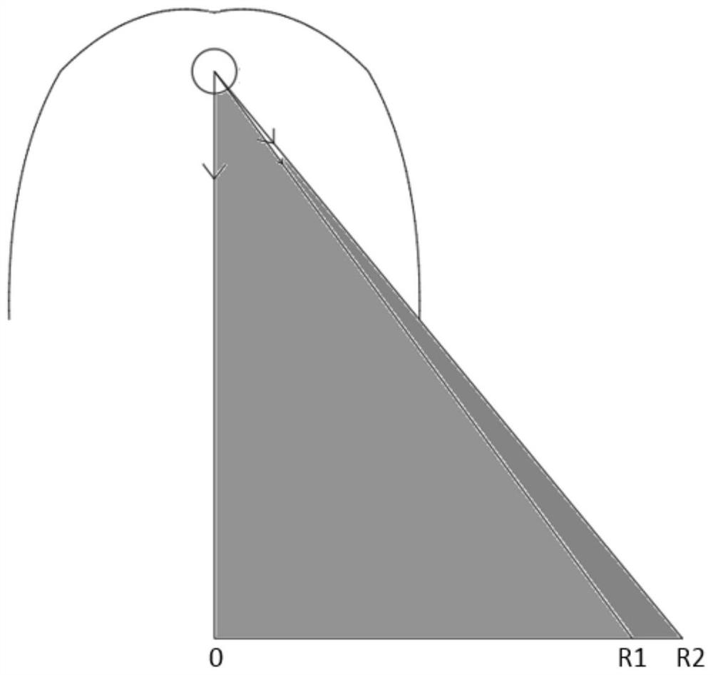
[0061] (1) Select an ultraviolet lamp with a diameter of 26.0mm, a length of 436.0mm, and a radiant energy of 4.0W as the light source, set the distance H=500mm from the illuminated surface to the exit point, and set the radius of the direct outgoing light from the exit point on the illuminated surface. The range O-R2 is 340mm, that is, a2=340mm;

[0062] (2) Calculate the boundary point R1 according to the energy distribution equation, where the light in the range of O-R1 is the superposition of the free outgoing light and the reflected light of the upper half of the reflector, and the light in the range of R1-R2 is the free outgoing light and the lower half of the light. The superposition of the reflected light of some reflectors, and to achieve uniform illumination after superposition, the first energy distribution equation is listed as:

[0063] Solve for a1=213.7152mm, and get th...


PUM


Abstract

The invention discloses a design and processing method for a reflector of a lamp tube. Specifically, the projection point O of the lamp tube is set, the boundary point R2 of the direct outgoing light from the exit point on the illuminated surface, and the boundary point R1 on the illuminated surface, so that The illuminance in the range of O-R1 is equal to the illuminance in the range of R1-R2, and the position of R1 is obtained according to the energy distribution equation; according to the principle that the energy emitted by the lamp is equal to the energy corresponding to the illuminance on the illuminated surface, the range of O-R1 is listed. The energy conservation equation in the range of R1-R2 and R1-R2 can be used to obtain the generatrix of the upper half curve and the lower half curve; the two are symmetrically copied through the ordinate to obtain the main curve of the reflector, and the main curve of the reflector is obtained by stretching the main curve of the reflector After that, the reflector can be obtained by performing certain processing according to the shape of the reflector body. The design method of the present invention adopts a free-form surface for optical design, the illuminance of the lamp tube is relatively evenly distributed in the cross-sectional direction, and the energy utilization rate of the lamp tube is improved; and the processing method is relatively simple and convenient for production.

Description

technical field [0001] The invention relates to a design method for a lamp reflector, in particular to a design and processing method for a one-way uniform lamp reflector based on a free-form surface. Background technique [0002] Different from the flat light-emitting surface of LED, traditional fluorescent lamps, mercury lamps, etc. can emit light at various angles, and the light-emitting surface is a cylindrical side illuminator. The illumination is not uniform enough; and there are not many secondary light distribution design methods for this type of lamps at present. In the existing fluorescent lamp design methods, most of the fluorescent lamp reflectors with trapezoidal side busbars are designed, followed by arc or symmetrical parabola, and some other devices with uniform light added under the reflector. The disadvantages of these secondary light distribution designs are: on the target lighting surface, either the illuminance distribution is uneven, the energy utiliza...

Claims


Application Information

Patent Timeline
Patent Type & Authority Patents(China)
IPC IPC(8): G02B27/00F21V7/04
CPCG02B27/0012F21V7/04
Inventor 庄正飞郭晋豪陈同生
Owner 师大瑞利光电科技(清远)有限公司
Learn More