Lens for panel lamp and panel lamp comprising lens
A flat lamp and lens technology, applied in the direction of light guides of lighting systems, components of lighting devices, semiconductor devices of light-emitting elements, etc.
- Summary
- Abstract
- Description
- Claims
- Application Information
AI Technical Summary
Problems solved by technology
Method used
Image
Examples
Embodiment 1
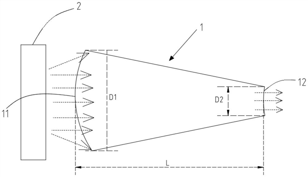
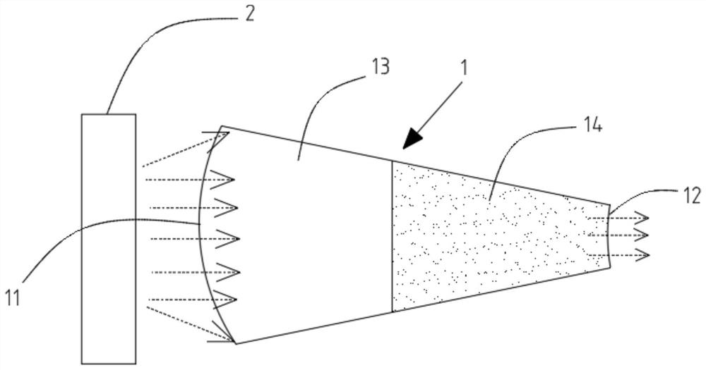
[0033] Embodiment 1: A kind of lens for panel light, such as figure 1 with 2 As shown, the lens 1 has a light incident surface 11 and a light exit surface 12, the light incident surface is convex, the light exit surface is concave, and the width of the light incident surface is greater than the width of the light exit surface;
[0034] The light emitted by the light source 2 enters the lens through the light-incident surface, is converged by the lens, and finally exits in parallel through the light-exit surface.
[0035] Such as figure 1 As shown, the lens is an integral lens made of the same material with the same refractive index.
[0036] Such as figure 2 As shown, the lens includes a first lens 13 and a second lens 14, the light incident surface of the first lens is convex, the light exit surface of the second lens is concave, the light exit surface of the first lens and the The incident surfaces of the second lens are spliced together.
[0037] The light exit surf...
Embodiment 2
[0042] Embodiment 2: A kind of lens for flat lamp, such as image 3 As shown, a flat panel lamp with the above-mentioned lens, the panel lamp includes an LED light source 3, a light guide plate 4, a reflective layer 5 and a back plate 7, and the back plate, the reflective layer and the light guide plate are sequentially Stacked, the LED light source is located on the side of the light guide plate, the lens is located between the LED light source and the light guide plate, and the light incident surface of the lens is close to the LED light source, and the light exit surface is close to the light guide plate.
[0043] In this embodiment, the flat panel lamp further includes a diffusion layer 6, and the diffusion layer is located on the side of the light guide plate away from the reflective layer.
[0044] Define the thickness of the light incident surface of the lens as D1 and the approximate radius of curvature R1, the thickness of the light exit surface of the lens as D2 and...
Embodiment 3
[0049] Embodiment 3: as Figure 4 As shown, the structure is similar to that of Embodiment 2, except that the panel lamp of this embodiment does not contain a diffusion layer, and the light guide plate includes a substrate 41, and the substrate has two opposite surfaces, which are respectively the front surface 411 and the The back side 412, and the front side is defined as the light-emitting surface, the back side is a frosted surface with a diffusion function for light, the frosted surface is an uneven rough surface formed by concave parts and convex parts, and the front side is hardened (here The treatment is the hard surface of the existing technology, such as surface coating or immersion, so it will not be described in detail);
[0050] There are several light guide points 413 inside the substrate. In this embodiment, the light guide points are located inside the substrate and on the side close to the frosted surface.
[0051] Preferably, the depth of the light guide poi...
PUM
 Abstract
Description
Claims
Application Information
 - R&D Engineer
- R&D Manager
- IP Professional
- Industry Leading Data Capabilities
- Powerful AI technology
- Patent DNA Extraction
Browse by: Latest US Patents, China's latest patents, Technical Efficacy Thesaurus, Application Domain, Technology Topic, Popular Technical Reports.
© 2024 PatSnap. All rights reserved.Legal|Privacy policy|Modern Slavery Act Transparency Statement|Sitemap|About US| Contact US: help@patsnap.com


