
Ultra-precision hydraulic control method

A control method and ultra-precise technology, applied in the direction of fluid pressure actuation device, fluid pressure actuation system test, fluid pressure actuation system components, etc., can solve the problem that higher precision is difficult to achieve, output precision is not high enough, and interference factors Many problems are solved to achieve the effects of accurate pressure measurement and temperature detection and control, good voltage regulation effect and low interference factor.

Pending Publication Date: 2021-05-07
SHANXI GAOHANG HYDRAULIC
View PDF6 Cites 1 Cited by
  • Summary
  • Abstract
  • Description
  • Claims
  • Application Information

AI Technical Summary

Problems solved by technology

[0002] Accurately controlled hydrostatic output is widely used in high-precision machining processes, such as hydrostatic bearings, hydrostatic guide rails, etc. At present, the precision of the precision hydraulic oil source control technology is generally greater than 1‰, and the accuracy of the constant pressure control is less than 1‰. High precision is difficult to achieve, or it is difficult to maintain stability. The existing oil source control circuit technology mostly uses high-precision proportional servo valves and / or more precisely controlled pumps to control the output oil pressure, but the stability is generally poor. , there are many interference factors, and the output accuracy is not high enough, which is not suitable for the production needs of industrialized precision manufacturing at this stage.

Method used


Image

  • Ultra-precision hydraulic control method
  • Ultra-precision hydraulic control method
  • Ultra-precision hydraulic control method

Examples


Embodiment Construction

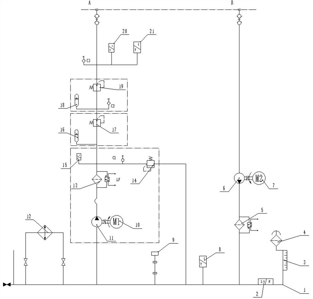
[0026] The ultra-precise hydraulic control circuit includes the oil supply circuit, oil return circuit and cooling circuit respectively connected to the oil tank 1;

[0027] Such as figure 1 , including an oil supply circuit, an oil return circuit, and a cooling circuit respectively connected to the oil tank 1;

[0028] Wherein, the oil supply circuit includes: a hydraulic pump 11 driven by the first servo motor 10, a pressure reducing valve, an accumulator, an overflow valve 14, and a high-pressure oil filter. The oil suction port of the hydraulic pump 11 is connected to the oil tank 1, and the outlet of the hydraulic pump 11 is connected to The high-pressure oil filter 13, the outlet of the high-pressure oil filter 13 is connected to the overflow valve 14, the oil return of the overflow valve 14 is connected to the oil tank 1, the accumulator includes a first accumulator 16 and a second accumulator 18, and the pressure reducing valve includes : the first pressure reducing v...


PUM


Abstract

The invention relates to a system for accurately controlling oil pressure, in particular to an ultra-precision hydraulic control method. The control method comprises the steps that pressure regulation is sequentially performed through three-stage pressure control, a servo motor is adopted for driving an oil-electricity servo control system of a screw pump in first-stage pressure stabilization, the servo motor is driven to work by a servo driver connected and controlled by a control center, a pressure sensor is arranged for feedback, and the system pressure is subjected to servo control PID regulation; in second-stage pressure stabilization, a high-precision first pressure reducing valve is used for reducing and stabilizing the pressure of the system, and the pressure of the system is subjected to wave absorption treatment; third-stage pressure stabilization is the same as second-stage pressure stabilization, and the system pressure is further subjected to wave absorption treatment through a high-precision second pressure reducing valve; and pressure stabilizers are arranged in the second stage and the third stage so as to reduce the influence of flow pulsation on pressure. Three-stage pressure control is adopted, so that the control precision is improved, stability is good, interference factors are low, pressure interference is reduced through cleanliness and temperature control, and pressure measurement detection and temperature detection control are accurate.

Description

technical field [0001] The invention belongs to the technical field of hydraulic precision control, in particular to an ultra-precision hydraulic control method. Background technique [0002] Accurately controlled hydrostatic output is widely used in high-precision machining processes, such as hydrostatic bearings, hydrostatic guide rails, etc. At present, the precision of the precision hydraulic oil source control technology is generally greater than 1‰, and the accuracy of the constant pressure control is less than 1‰. High precision is difficult to achieve, or it is difficult to maintain stability. The existing oil source control circuit technology mostly uses high-precision proportional servo valves and / or more precisely controlled pumps to control the output oil pressure, but the stability is generally poor. , there are many interference factors, and the output accuracy is not high enough, which does not meet the needs of industrialized precision manufacturing at this s...

Claims


Application Information

Patent Timeline
Patent Type & Authority Applications(China)
IPC IPC(8): F15B11/17F15B1/02F15B13/02F15B19/00F15B21/041F15B21/042F15B21/08
CPCF15B11/17F15B1/02F15B13/025F15B13/02F15B19/00F15B21/041F15B21/042F15B21/08
Inventor 王朝林张正宁屈鹏飞
Owner SHANXI GAOHANG HYDRAULIC
Learn More