
Uniform wooden stick polishing device

A uniform and stick technology, applied in the direction of grinding drive device, grinder, grinding frame, etc., can solve the problems that new employees are not easy to control the grinding allowance of wooden sticks, and the grinding efficiency is low, so as to achieve the convenient grinding allowance. , Improve the grinding effect, reduce the effect of vibration

Active Publication Date: 2021-04-30
NANJING YUQUN COMM TECH CO LTD
View PDF16 Cites 0 Cited by
  • Summary
  • Abstract
  • Description
  • Claims
  • Application Information

AI Technical Summary

Problems solved by technology

[0004] In order to overcome the disadvantages of manually controlling the movement of the wooden stick during the whole process, the grinding efficiency is low, and it is difficult for new employees to control the grinding allowance of the wooden stick. Wood stick even grinding device

Method used


Image

  • Uniform wooden stick polishing device
  • Uniform wooden stick polishing device
  • Uniform wooden stick polishing device

Examples


Embodiment 1

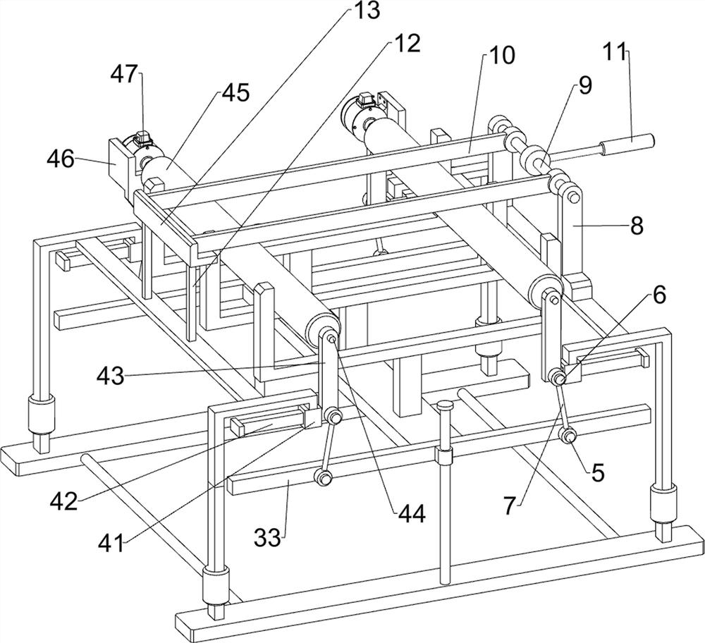
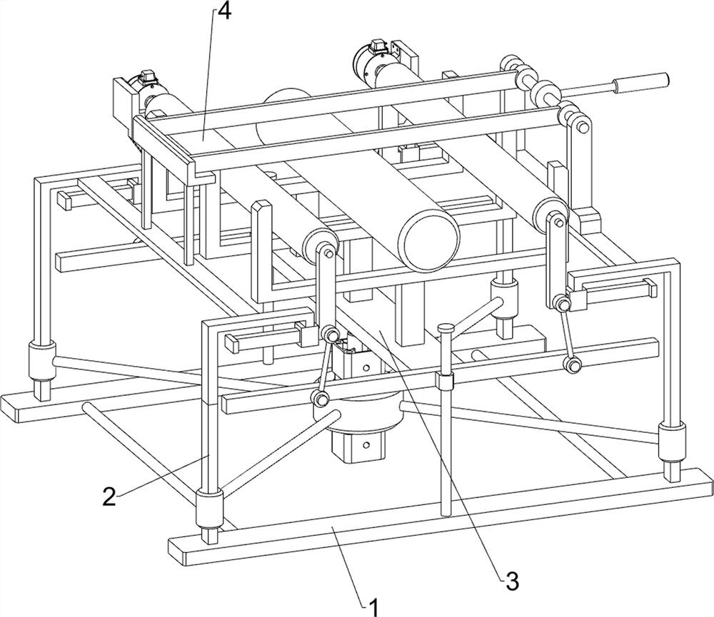
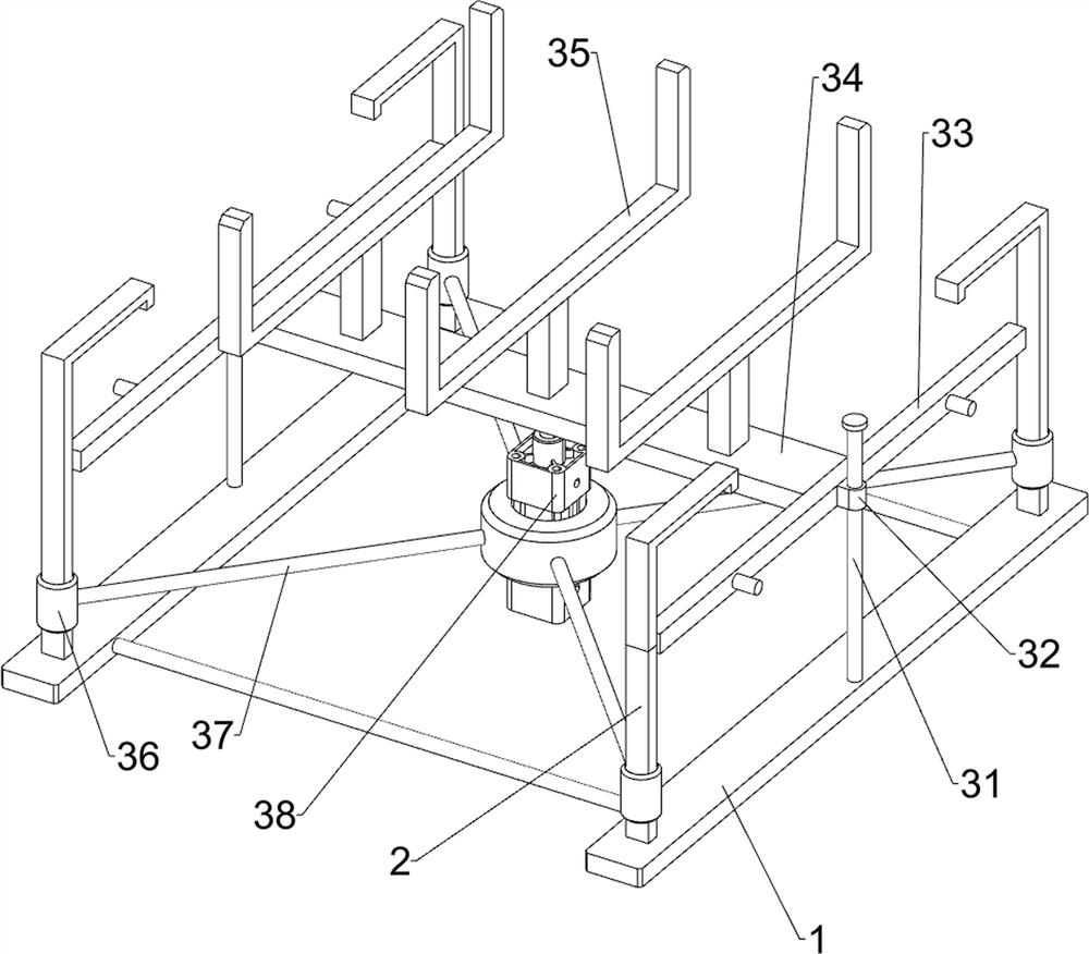
[0020] like figure 1 , figure 2 and image 3 As shown, a wooden stick uniform grinding device includes a base plate 1, a bracket 2, a lifting mechanism 3 and a grinding mechanism 4, a bracket 2 is evenly arranged around the top of the base plate 1, a lifting mechanism 3 is arranged in the middle of the top of the base plate 1, and a lifting mechanism 3 is arranged on the top of the bracket 2. A grinding mechanism 4 is provided.

[0021] The lifting mechanism 3 includes a guide rod 31, a first slide block 32, a push rod 33, a connecting block 34, a first placing block 35, a first fixing block 36, a first fixing rod 37 and a hydraulic cylinder 38, and the bottom plate 1 is arranged symmetrically in the middle There are two guide rods 31, the guide rod 31 is provided with a first slide block 32, one side of the first slide block 32 is provided with a push rod 33, a connection block 34 is fixedly connected between the two push rods 33, and the top of the connection block 34 Th...

Embodiment 2

[0025] like image 3 As shown, on the basis of Embodiment 1, a second fixed rod 5, a third fixed rod 6 and a connecting rod 7 are also included, and the push rod 33 is symmetrically provided with the second fixed rod 5 near the side of the guide rod 31. The side of the second slider 42 close to the first bearing seat 43 is provided with a third fixed rod 6 , and the second fixed rod 5 and the third fixed rod 6 are hingedly connected by a connecting rod 7 .

[0026] In addition, when the hydraulic cylinder 38 drives the connecting block 34 to move upward, the push rod 33 drives the connecting rod 7 hinged therewith to move the first bearing seat 43 to move inward, and the two first bearing seats 43 drive the grinding mechanism respectively. 4. The overall movement is inward, which can fully meet the grinding needs of wooden sticks with different diameters, and at the same time, it is convenient to control the grinding allowance.

[0027] It also includes a second bearing seat ...


PUM


Abstract

The invention relates to polishing equipment, in particular to a uniform wooden stick polishing device. The uniform wooden stick polishing device is full-automatic in polishing and can conveniently control the polishing allowance. The uniform wooden stick polishing device comprises a bottom plate, a lifting mechanism and a polishing mechanism, wherein supports are evenly arranged on the periphery of the top of the bottom plate; the lifting mechanism is arranged in the middle of the top of the bottom plate; and the polishing mechanism is arranged at the top of the supports. When first placing blocks supports a wooden stick to make contact with two polishing rollers, the wooden stick is driven to rotate under the action of rotating force and extrusion force, the wooden stick rotates, slides and is ground in the two polishing rollers rotating in the opposite directions, in this way, manual intervention is not needed in the polishing process, and full-automatic polishing is achieved.

Description

technical field [0001] The invention relates to a grinding device, in particular to a wooden stick uniform grinding device. Background technique [0002] When designing and manufacturing wooden furniture, wooden sticks are used in many products, so in order to meet market requirements in all aspects of wooden sticks, it is necessary to polish the wooden sticks, and remove some unnecessary impurities or other substances on the surface of wooden sticks or Grinding the thickness of the wooden stick, and for the sake of beauty, there are usually certain requirements for the smoothness of the wooden stick. [0003] Nowadays, the grinding method generally adopts the abrasive belt grinding machine, which requires manual hand-held wooden sticks to slowly approach the fixed high-speed rotating abrasive belt. The movement of the wooden stick needs to be manually controlled throughout the process. The grinding efficiency is low, and the grinding needs to be controlled by experienced ma...

Claims


Application Information

Patent Timeline
Patent Type & Authority Applications(China)
IPC IPC(8): B24B5/04B24B5/50B24B5/35B24B41/06B24B41/02B24B47/14B24B47/12
CPCB24B5/04B24B5/50B24B5/35B24B41/06B24B41/02B24B47/14B24B47/12Y02P70/10
Inventor 罗仕兵
Owner NANJING YUQUN COMM TECH CO LTD
Learn More