A trolley for grinding positioning pin holes of pile legs and grinding method thereof
A technology for positioning pin holes and grinding trolleys, which is applied to grinding machines, parts of grinding machine tools, grinding/polishing equipment, etc. It can solve the problems of low automation and low precision, achieve convenient equipment installation, improve production efficiency, and eliminate the need for The effect of positioning measurements
- Summary
- Abstract
- Description
- Claims
- Application Information
AI Technical Summary
Problems solved by technology
Method used
Image

Examples
Embodiment 1
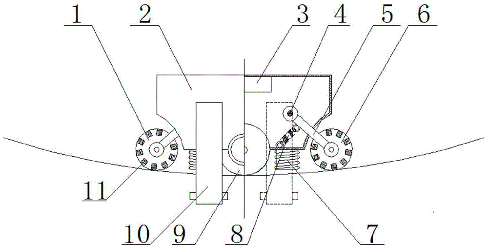
[0026] see Figure 1-4 , the present invention provides a trolley for grinding the positioning pin holes of pile legs, comprising a trolley box body 2, a front drive wheel 1, a rear drive wheel 6, a control module 3, an internal connecting rod 4, a drive wheel support rod 5, a grinding wheel 9, and a guide wheel Support 10, adsorption coil 11, transmission shaft 19, bearing box 13, guide wheel 14 and motor 15.
[0027] Wherein the inner connecting rod 4 is located in the trolley box body 2, and the front driving wheel 1 and the rear driving wheel 6 are connected with the connecting rod 4 through the driving wheel support rod 5; 19 drives the grinding wheel 9 to rotate; the grinding wheel 9 is connected to the bearing boxes 13 located on both sides of the trolley case 2 through the transmission shaft 19, and the grinding wheel 9 is fixed below the trolley case 2; at least two pairs of guide wheel brackets are connected to the two sides of the trolley case 2 10. The lower end o...
Embodiment 2
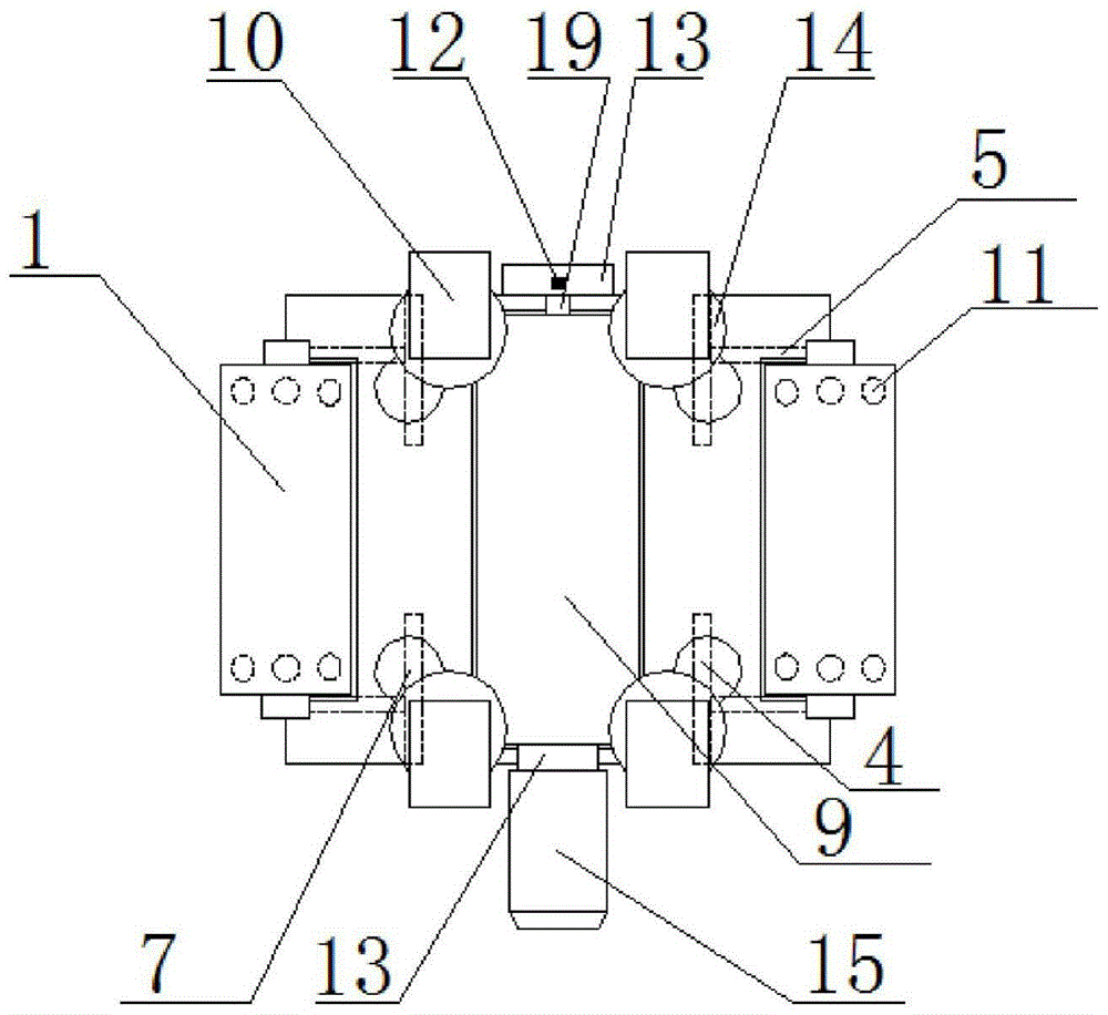
[0029] see Figure 1-4 , the present invention provides a grinding trolley for positioning pin holes of pile legs, comprising a grinding trolley 20, a front driving wheel 1, a trolley box body 2, a control module 3, an internal connecting rod 4, a driving wheel support rod 5, a rear driving wheel 6, a pressure Adjustment coil 7, internal tension spring 8, grinding wheel 9, guide wheel support 10, adsorption coil 11, pressure sensor 12, transmission shaft 19, bearing box 13, guide wheel 14, motor 15, external spring 16, hinged hole composition 18.
[0030] The two ends of the front driving wheel 1 and the rear driving wheel 6 are arranged with a plurality of adsorption coils 11 in a circumferential manner, which are used to generate suction, and the grinding trolley 20 is adsorbed to the inner surface 17 of the positioning pin hole. The control module 3 positioned at the top of the trolley casing 2 controls the adsorption coils 11 in the front drive wheel 1 and the rear drive w...
Embodiment 3
[0032] see Figure 1-4 , the present invention also provides a kind of grinding method that adopts described leg positioning pin hole grinding trolley, specifically as follows:
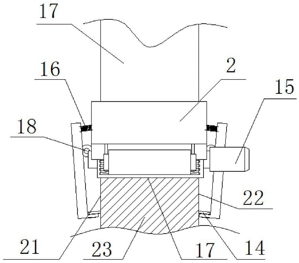
[0033] 1. Open the guide wheel bracket 10, place the grinding trolley 20 on the inner surface 17 of the positioning pin hole of the leg; make the front driving wheel 1 and the rear driving wheel 6 contact the inner surface 17 of the positioning pin hole; close the guide wheel bracket 10, and make the The guide wheels 14 are respectively in close contact with the inner wall 22 and the outer wall 21 of the legs.
[0034] 2. The control module 3 controls the suction coil 11 to generate suction force, and adsorbs the grinding trolley 20 to the inner surface 17 of the positioning pin hole.
[0035] 3. The control module 3 controls the adsorption coils 11 in the front drive wheel 1 and the rear drive wheel 6 to make the front drive wheel and the rear drive wheel rotate.
[0036] 4. Turn on the motor 15 to...
PUM
 Abstract
Description
Claims
Application Information
 - R&D
- Intellectual Property
- Life Sciences
- Materials
- Tech Scout
- Unparalleled Data Quality
- Higher Quality Content
- 60% Fewer Hallucinations
Browse by: Latest US Patents, China's latest patents, Technical Efficacy Thesaurus, Application Domain, Technology Topic, Popular Technical Reports.
© 2025 PatSnap. All rights reserved.Legal|Privacy policy|Modern Slavery Act Transparency Statement|Sitemap|About US| Contact US: help@patsnap.com