Molten iron splash-proof energy-saving device for mining and metallurgy machining

An energy-saving device and molten iron technology, applied in the field of mining and metallurgy processing, can solve problems such as punching out of the mold, waste of molten iron, and inability to enter the molten iron normally

Inactive Publication Date: 2021-04-30
商都中建金马冶金化工有限公司
View PDF8 Cites 0 Cited by
  • Summary
  • Abstract
  • Description
  • Claims
  • Application Information

AI Technical Summary

Problems solved by technology

[0005] At the position of the molten iron inlet 2 at the right end of the molten iron tank 1, there is no baffle plate, which will cause the molten iron to fail to enter the mold 3 normally or directly rush out of the mold 3 when the flow rate of the molten iron is too large, which causes the waste of molten iron;

Method used


Image

  • Molten iron splash-proof energy-saving device for mining and metallurgy machining
  • Molten iron splash-proof energy-saving device for mining and metallurgy machining
  • Molten iron splash-proof energy-saving device for mining and metallurgy machining

Examples


Embodiment 1

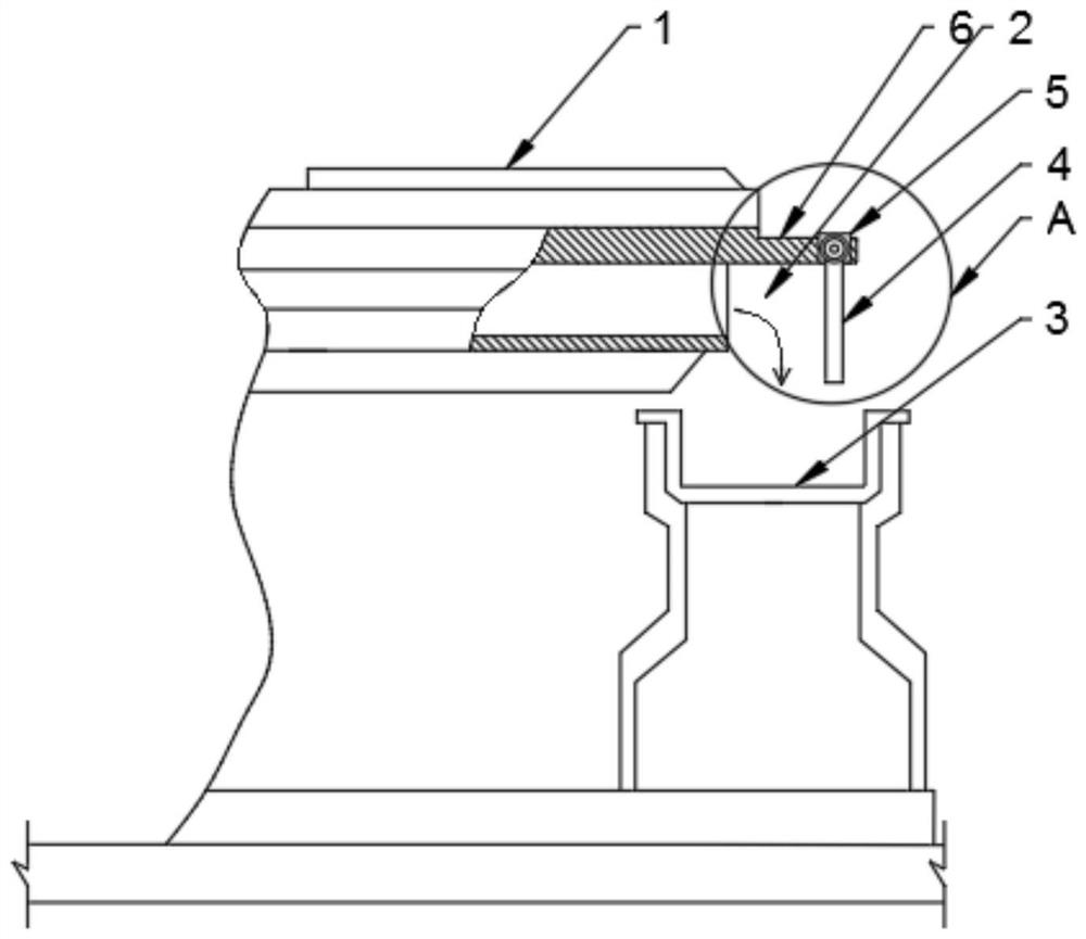
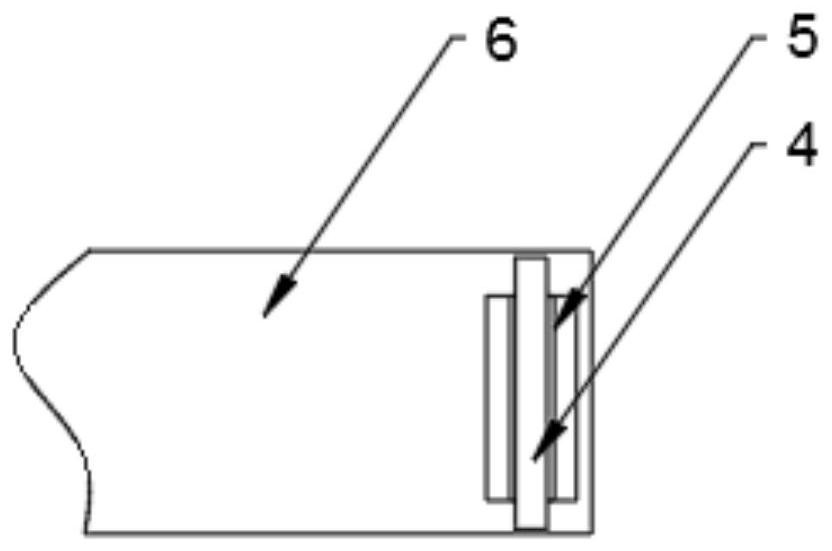
[0038] An anti-splash energy-saving device for molten iron in mining and metallurgy processing, comprising a molten iron tank 1 with a molten iron inlet 2 and a mold 3, the molten iron tank 1 where the molten iron inlet 2 is located is provided with an articulated plate 6, and the articulated plate 6 is There is a baffle 4 located on the right side of the molten iron inlet 2, and the longitudinal projection of the baffle 4 is located in the mold 3; the left side of the baffle 4 is provided with an anti-sticking coating.

[0039] In this embodiment, a baffle plate 4 is arranged on the molten iron tank 1 to buffer the impact of the molten iron.

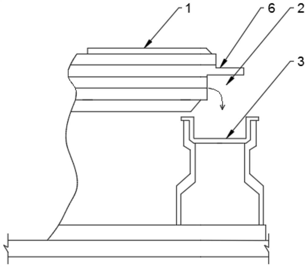
[0040] as attached Figure 2-3 As shown, the present invention provides an energy-saving device for preventing splashing of molten iron in mining and metallurgy processing, which includes a molten iron tank 1 with a molten iron inlet 2 and a mold 3. The mold 3 is located below the molten iron inlet 2 to facilitate receiving molten iron....

Embodiment 2

[0068] An anti-splash energy-saving device for molten iron in mining and metallurgy processing, comprising a molten iron tank 1 with a molten iron inlet 2 and a mold 3, the mold 3 is provided with a baffle 4 on the right side of the molten iron inlet 2, and the left side of the baffle 4 The longitudinal projection of the side is located in the mold 3; the left side of the baffle 4 is provided with an anti-sticking coating.

[0069] As another usage mode of the present invention, the baffle plate 4 is also used in the anti-splash mode, but it is arranged on the mold 3 .

[0070] as attached Figure 6 As shown, a baffle plate 4 is installed on the top surface of the main body on the right side of the mold 3 and fixed by bolts. But in order for molten iron to enter normally, the longitudinal projection of the left side of the baffle plate 4 needs to be located in the mold 3 .

[0071] Similar to Embodiment 1, the left side of the baffle plate 4 is provided with an anti-sticking...


PUM

PropertyMeasurementUnit
thicknessaaaaaaaaaa

Abstract

The invention discloses a molten iron splash-proof energy-saving device for mining and metallurgy machining. The molten iron splash-proof energy-saving device for mining and metallurgy machining comprises a molten iron tank with a molten iron inlet and a mold, a hanging plate is arranged on the molten iron tank where the molten iron inlet is located, a baffle located on the right side of the molten iron inlet is arranged on the hanging plate, the longitudinal projection of the baffle is located in the mold, and an anti-sticking coating is arranged on the left side face of the baffle. According to the molten iron splash-proof energy-saving device for mining and metallurgy machining, a molten iron baffle structure with a wall-breaking anti-sticking coating function is arranged on the molten iron tank or the mold, and therefore molten iron splashing can be effectively prevented, and molten iron waste is avoided; the baffle is practical, is priority used on the molten iron tank and is movably arranged, and therefore backflushing can be achieved under the elastic action of an elastic piece, and impact of the molten iron can be effectively buffered when the flow speed of the molten iron is too large; and in addition, the movably connected baffle can be convenient to overhaul.

Description

technical field [0001] The present application relates to the technical field of mining and metallurgy processing, in particular to an energy-saving device for splash prevention and energy saving of molten iron in mining and metallurgy processing. Background technique [0002] During the iron and steel smelting process, if attached figure 1 As shown, the molten iron in the high-temperature furnace needs to be guided from the molten iron tank 1 into the mold 3, and the mold 3 is used for billet casting to facilitate post-processing. [0003] The right end of the molten iron tank 1 is the molten iron inlet 2, and the molten iron rushes out or flows out from the molten iron inlet 2 and enters the corresponding mold 3 below. [0004] And find in practice, it has the following technical problems: [0005] At the position of the molten iron inlet 2 at the right end of the molten iron tank 1, there is no baffle plate, which will cause the molten iron to fail to enter the mold 3 n...

Claims


Application Information

Patent Timeline
Patent Type & Authority Applications(China)
IPC IPC(8): B22D35/04
CPCB22D35/04
Inventor 刘日宏
Owner 商都中建金马冶金化工有限公司
Why Eureka
Try Eureka