A selective wave-absorbing surface structure and its preparation method

A surface structure and selective technology, applied in the direction of antennas, electrical components, etc., can solve the problems of poor stealth effect and inability to completely filter out electromagnetic waves, so as to improve the effect of stealth and enhance the effect of selective absorption

Active Publication Date: 2022-05-10
XIAN MICROMACH TECH CO LTD
View PDF11 Cites 0 Cited by
  • Summary
  • Abstract
  • Description
  • Claims
  • Application Information

AI Technical Summary

Problems solved by technology

[0004] However, the frequency selective layer of this method has a certain transmittance and cannot completely filter out non-operating frequency electromagnetic waves, so there is a problem of poor stealth effect

Method used


Image

  • A selective wave-absorbing surface structure and its preparation method
  • A selective wave-absorbing surface structure and its preparation method
  • A selective wave-absorbing surface structure and its preparation method

Examples


Embodiment 1

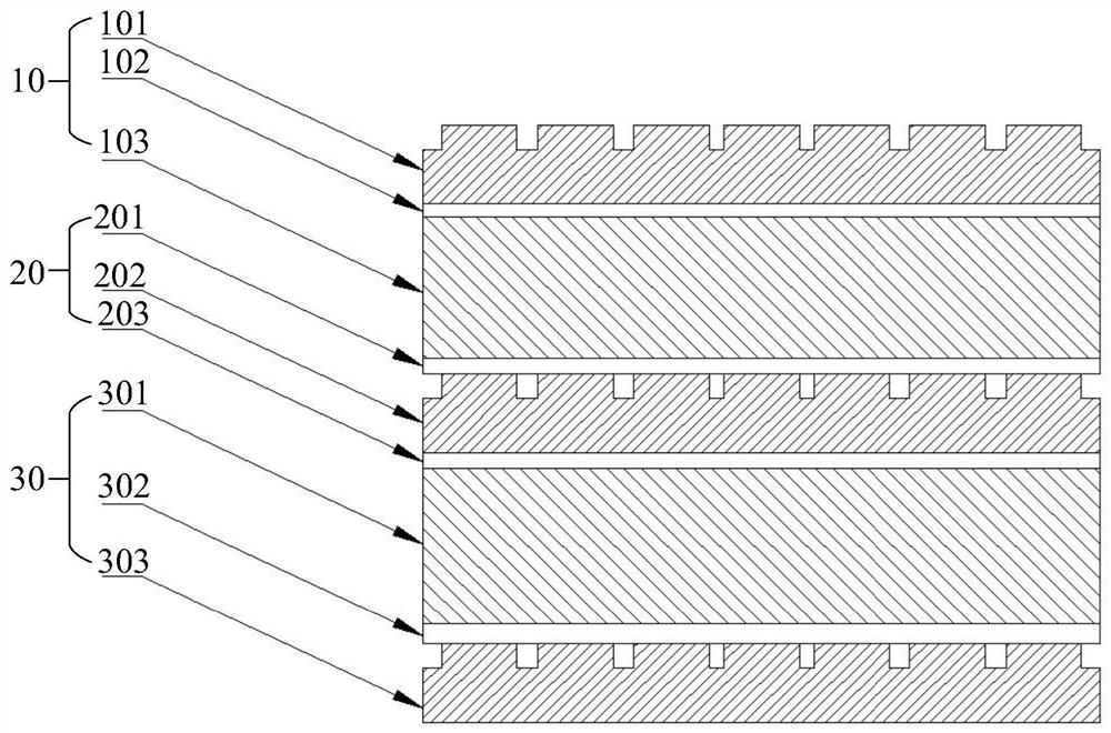
[0049] See figure 1 , figure 1 It is a structural schematic diagram of a selective wave-absorbing surface structure provided by an embodiment of the present invention. An embodiment of the present invention provides a selective wave-absorbing surface structure, the selective wave-absorbing surface structure may include: a frequency selective structure 10, at least one reflective structure 20 and a reinforcement structure 30, wherein the frequency selective structure 10 is located on the reflective structure 20 Above, the reflection structure 20 is located on the enhancement structure 30. In addition, when the number of reflection structures 20 is two or more, multiple reflection structures 20 are arranged on the frequency selective structure 10 and the enhancement structure 30 in a stacked manner. Between, the frequency selective structure 10 can transmit the electromagnetic wave of the working frequency, and can also reflect the electromagnetic wave of the first non-working ...

Embodiment 2

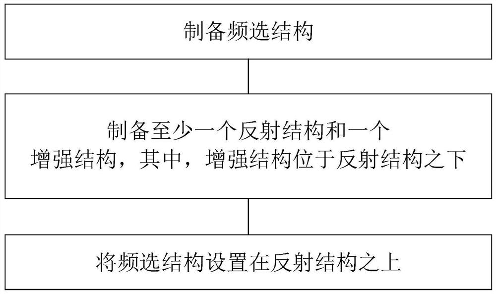
[0089] See image 3 , image 3 It is a schematic flowchart of a method for preparing a selective wave-absorbing surface structure provided by an embodiment of the present invention. This embodiment provides a method for preparing a selective wave-absorbing surface structure on the basis of the above-mentioned embodiments, the preparation method comprising:

[0090] Step 1, see Figure 4a , to prepare the frequency-selective structure 10.

[0091] Step 1.1: Plating a first intermediate layer 102 on the first dielectric layer 103 by using a coating process.

[0092]Preferably, the material of the first intermediate layer 102 is a connection material with high transmittance, which may be a polymer material, such as polyimide.

[0093] Preferably, the thickness of the first intermediate layer 102 ranges from 0 to 0.1 mm.

[0094] Preferably, the material of the first dielectric layer 103 is a non-metallic dielectric material with a dielectric constant of 0-20, such as ceramic...


PUM


Abstract

The invention discloses a selective wave-absorbing surface structure and a preparation method thereof. The surface structure includes a frequency-selective structure, at least one reflection structure and a reinforcement structure; wherein, the reflection structure is located under the frequency-selection structure, and the reinforcement structure is located under the frequency-selection structure. under the reflective structure described above. In the present invention, a reflection structure capable of reflecting non-operating frequency electromagnetic waves missed by the frequency selection structure and a corresponding microstructure are arranged between the frequency selection structure and the enhancement structure, thereby enhancing the selective absorption of the operating frequency and avoiding the Electromagnetic waves of non-operating frequencies enter the target object.

Description

technical field [0001] The invention belongs to the technical field of radar absorbing, and in particular relates to a selective absorbing surface structure and a preparation method thereof. Background technique [0002] With the increasing demand for radar stealth, the stealth absorbing technology of radome has attracted much attention. On the one hand, the radome needs to meet the stealth requirement, that is, the high reflection requirement of electromagnetic waves, and on the other hand, it needs to meet the microwave absorption requirement of the working frequency, that is, to High absorption requirements for electromagnetic waves in the working frequency band. [0003] At present, there are two solutions to the composite requirements of stealth and wave absorption of the radome. One way is to develop new materials and achieve the stealth and wave absorption requirements of composite materials by doping various elements in the material. It is difficult and costly, and ...

Claims


Application Information

Patent Timeline
Patent Type & Authority Patents(China)
IPC IPC(8): H01Q15/00H01Q17/00
CPCH01Q15/0026H01Q17/00
Inventor 王宁张满军刘超王自
Owner XIAN MICROMACH TECH CO LTD
Why Eureka
Try Eureka