Stamping device for automobile exhaust pipe

A stamping device, automobile exhaust technology, applied in the field of exhaust pipe stamping, to achieve the effect of convenient cutting and polishing, and improve the effect of cutting and polishing

Pending Publication Date: 2021-04-23
芜湖同创模具机械有限公司
View PDF10 Cites 0 Cited by
  • Summary
  • Abstract
  • Description
  • Claims
  • Application Information

AI Technical Summary

Problems solved by technology

[0003] Aiming at the inconvenient demoulding of existing stamping and forging, which is prone to burrs and inconvenient to deal with, the present invention provides an automobile exhaust pipe stamping device, which includes a base, a motor, a bearing, a rotating disc, a hydraulic device, a top plate, a Devices such as blue plate, support plate, extruded plate, and sand plate effectively solve the problems raised in the background technology

Method used


Image

  • Stamping device for automobile exhaust pipe
  • Stamping device for automobile exhaust pipe
  • Stamping device for automobile exhaust pipe

Examples


Embodiment 1

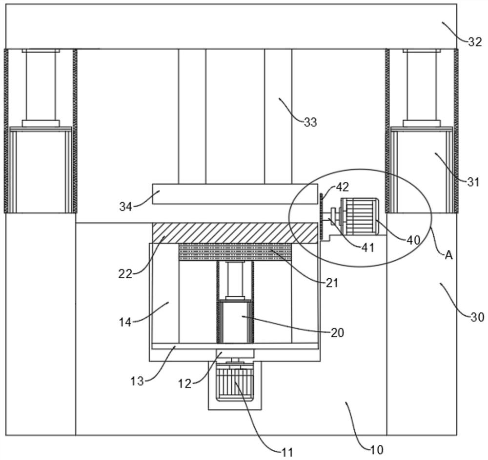
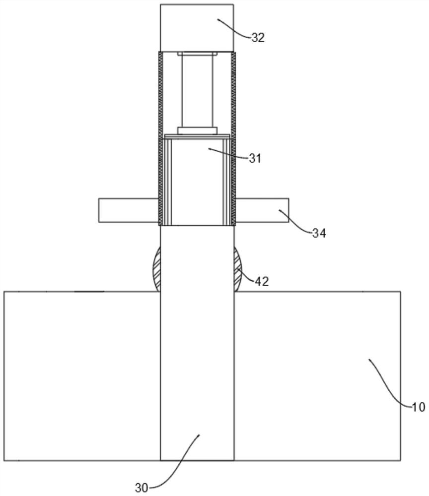
[0026] Such as Figure 1~3 As shown, it is a front view structural schematic diagram of an automobile exhaust pipe stamping device in a preferred embodiment of the present invention. The automobile exhaust pipe stamping device of this embodiment includes a base 10, and the inside of the base 10 is provided with a first Motor 11, the upper end of the first motor 11 is rotatably connected with a bearing 12, the upper end of the bearing 12 is connected with a rotating disk 13, the upper end of the rotating disk 13 is provided with a first hydraulic device 20, and the first The upper end of the hydraulic device 20 is provided with a top plate 21, the vertical centerline of the first hydraulic device 20 coincides with the vertical centerline of the rotating disk 13, the rotating disk 13 is connected with a supporting platform 14, and the supporting platform 14, the inner side surface is connected with the top plate 21, the top plate 21 and the support platform 14 are in a clearance...

Embodiment 2

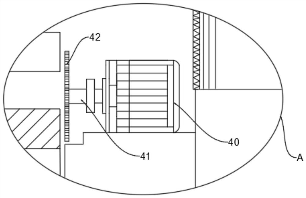
[0031] Such as Figure 4-5 As shown, it is a schematic diagram of a three-dimensional structure of a chute and a work piece in another preferred embodiment of the present invention. On the basis of Example 1, the chute and work shape of the automobile exhaust pipe stamping device of this embodiment The structure of the parts includes a second motor 40, the lower end of the second motor 40 is connected with a work piece 43, and the work piece 43 is slidably connected with a chute 44, and the work piece 43 and the chute 44 There is a gap fit relationship;

[0032] The working principle of the present invention is: the second motor 40 can move along the direction of the inner groove of the chute 44 through the said workpiece 43 and the chute 44, so as to adjust the distance between the sand disc 42 and the flange 22. The distance between them improves the cutting and grinding effect of the sand disc 42 on the extrusion and overflow flash of the flange plate 22.


PUM


Abstract

The invention discloses a stamping device for an automobile exhaust pipe, and belongs to the technical field of exhaust pipe stamping. The stamping device comprises a base, a first motor is arranged in the base, the upper end of the first motor is rotationally connected with a bearing, the upper end of the bearing is connected with a rotating disc, the upper end of the rotating disc is provided with a first hydraulic device, an ejection plate is arranged at the upper end of the first hydraulic device, a supporting table is connected to the rotating disc, the inner side surface of the supporting table is connected with the ejection plate, the ejection plate and the supporting table are in clearance fit, and a flange plate is connected to the upper end of the ejection plate; flashes which are extruded by the flange plate to overflow are cut and polished through an abrasive disc; and the cut and polished flange plate is ejected out of a groove through the ejection plate, demolding of the flange plate is completed, the distance between the abrasive disc and the flange plate is adjusted through an I-shaped piece and a sliding groove, and the cutting and polishing effect of the abrasive disc is improved.

Description

technical field [0001] The invention belongs to the technical field of exhaust pipe stamping, and in particular relates to an automobile exhaust pipe stamping device. Background technique [0002] Stamping is a pressure processing method that uses a mold installed on a press to apply pressure to the material at room temperature to cause separation or plastic deformation to obtain the required parts. In the manufacturing process of the automobile exhaust system, relatively The multi-component mechanism needs to be stamped to meet the assembly needs, including the stamping of the exhaust pipe flange. In the production and molding process of the automobile exhaust pipe flange, the flange is generally stamped and forged, but stamping Forging demoulding is inconvenient, and it is easy to have flash, which is inconvenient to handle, resulting in low production quality and production efficiency. Contents of the invention [0003] Aiming at the inconvenient demoulding of existing...

Claims


Application Information

Patent Timeline
Patent Type & Authority Applications(China)
IPC IPC(8): B21D22/02B21D19/00B21D53/84B24B27/06B24B9/04
CPCB21D22/02B21D19/005B21D53/84B24B27/06B24B27/0683B24B9/04
Inventor 陶文
Owner 芜湖同创模具机械有限公司
Why Eureka
Try Eureka