Optical device, system and optical apparatus
A technology of optical devices and optical systems, applied in optical components, optics, instruments, etc., can solve the problems of poor system flexibility, difficulty in realizing light field display, and can not replace lens/reflector light compression or expansion, etc., and achieve volume reduction. Effect
- Summary
- Abstract
- Description
- Claims
- Application Information
AI Technical Summary
Problems solved by technology
Method used
Image

Examples
Embodiment 1
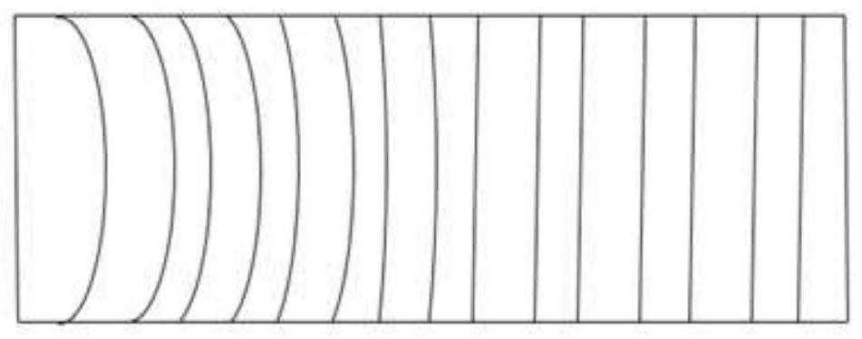
[0048] Such as Figure 1a , 1b , 1c, the present embodiment is used as a combiner in an augmented reality display system, and is composed of two Fresnel lenses with tooth surfaces fitted (gluing or bonding for the convenience of production, the Fresnel lenses The teeth can be of equal height, and the size of each tooth can be between 10 and 30 microns. The teeth here can be a single tooth, or a row or column of teeth in a one-dimensional direction, or teeth with the same center. Ring or belt, or a combination of the above forms), the optical parameters corresponding to each tooth can be designed independently (for example, the curvature corresponding to each tooth is different), and one Fresnel lens fits with the other Fresnel lens The surface is coated with an angle-selective AR coating. One side of one of the Fresnel lenses is glued with a dielectric waveguide, the refractive index of which is the same as or close to that of the Fresnel lens. Incidence from one side of the...
Embodiment 2
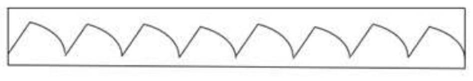
[0057] Such as Figure 7 As shown, another combiner in an augmented reality display system is made of two sheets with matching structures on each side surface (it can be a structure with a certain diopter designed off-axis, or a periodically repeated microstructure ) optical device, wherein the surface of one device and the other device is coated with a polarization-selective anti-reflection film. The image light is linearly polarized light (for example, the pixel uses an LCOS device, and the image light is P light relative to the tooth surface of the Fresnel lens), incident from one side of a device, when it enters the interface of two devices, it is completely reflective (or partially reflective in some embodiments, such as 50% reflective). Ambient light is incident from one side of another device, and when it is incident on the interface of two devices, the S component with the polarization direction is completely transmitted (or it can be mostly transmitted, such as 95%),...
Embodiment 3
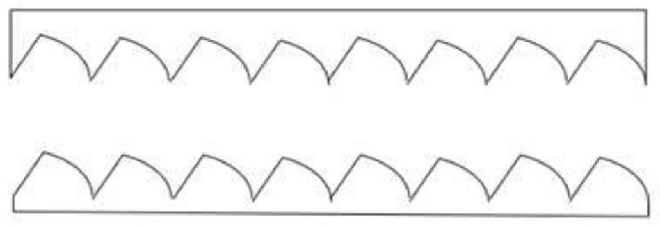
[0062] Such as Figure 8 As shown in , another combiner in an augmented reality display system is composed of two optical devices with matching tooth-shaped structures prepared on each side surface. The image light is incident from a surface of a piece of structure at a certain angle range, and then reaches its tooth-shaped surface after passing through the structure. For light rays, these tooth-shaped structures are equivalent to mirrors with certain optical parameters (radius of curvature, conic coefficient, high-order terms of aspheric surfaces, etc.). The surface opposite to the incident direction of the image light is coated with an anti-reflection coating (if the refractive index of the two devices is close to or the same, the anti-reflection coating may not be coated), the external ambient light is incident from another device, and passes through the other device. When a piece of device reaches the interface, the light incident on the surface coated with anti-reflectio...
PUM
 Abstract
Description
Claims
Application Information
 - R&D
- Intellectual Property
- Life Sciences
- Materials
- Tech Scout
- Unparalleled Data Quality
- Higher Quality Content
- 60% Fewer Hallucinations
Browse by: Latest US Patents, China's latest patents, Technical Efficacy Thesaurus, Application Domain, Technology Topic, Popular Technical Reports.
© 2025 PatSnap. All rights reserved.Legal|Privacy policy|Modern Slavery Act Transparency Statement|Sitemap|About US| Contact US: help@patsnap.com