Pipe fixing method suitable for permafrost regions
A technology for fixing pipelines and permafrost areas, applied in soil protection, pipeline laying and maintenance, pipes/pipe joints/fittings, etc., can solve problems such as instability, frost heaving, solar power supply, and thawing, and achieve easy assembly, The effect of various functions and high degree of integration
- Summary
- Abstract
- Description
- Claims
- Application Information
AI Technical Summary
Problems solved by technology
Method used
Image
Examples
Embodiment 1
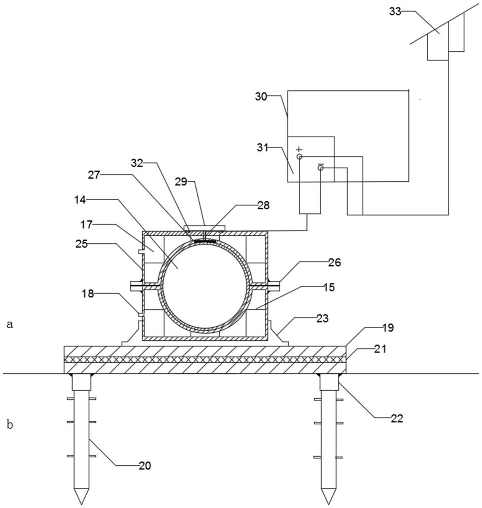
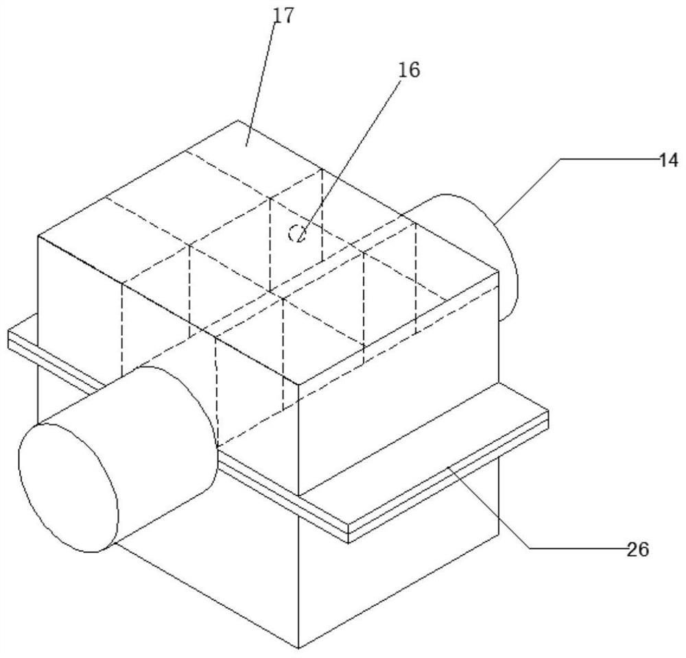
[0042] A pipeline fixed installation system based on energy recovery, the pipeline is fixed on the heat insulation installation plate through the heat insulation fixing component, the heat insulation installation plate is fixed above the permafrost layer through the antifreeze pulling support legs, the heat insulation The fixing assembly includes two positioning installation parts up and down, and the two positioning installation parts are butted to form a circular channel for the pipeline 14 to pass through;
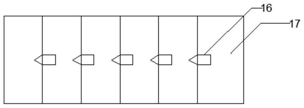
[0043] Each positioning installation part includes a shell plate 25 that forms a sealed chamber inside, and an energy recovery component is provided on the fixed mounting part, and the energy recovery component includes a fixed part at the bottom of the shell plate 25 and can be closely attached to the The semiconductor power generation sheet 27 on the outer wall of the pipeline 14, the top of the semiconductor power generation sheet 27 is connected with the cold plate 2...
Embodiment 2
[0053] Preferably, the heat insulating mounting board includes two layers of mounting boards 19 and a heat insulating board 21 sandwiched between the two layers of mounting boards 19 . The thermal insulation mounting plate can prevent the heat of the crude oil pipeline from being transferred into the permafrost, resulting in degradation of the permafrost in contact with the crude oil pipeline.
[0054] Preferably, the installation board 19 is a metal board, and the heat insulation board 21 is a rigid polyethylene fiber board. Guarantee the strength and heat insulation performance of the heat insulation mounting plate.
[0055] As preferably, a connection plate 26 is fixed on the position where the two fixed installation parts are connected. After the two fixed installation parts are butted, they are fixedly connected by the connection plate. After 26 are fastened together, it can ensure that the shell plate 25 and the pipe 14 fit closely.
[0056] Preferably, a mounting base...
Embodiment 3
[0062] Preferably, the support leg body 5 and the expansion inner core are included, wherein a hollow channel is formed inside the support leg body 5, and at least one side wall through hole is provided on the side wall of the support leg body 5, and each side wall A frozen nail 4 is assembled in the through hole; the expansion inner core includes a fixed transparent cover 3 detachably assembled on the top of the supporting leg body 5, and an embedded insulating wire sleeve fixed in the central opening of the fixed transparent cover 3 8. The frozen nail pusher 6 fixed on the bottom of the insulating wire sleeve 8 and located in the hollow channel, and the frozen nail pusher 7 cooperating with the frozen nail pusher 6; the frozen nail pusher 7 includes a push rod part 7-1 that is partly inserted in the frozen nail push sleeve 6 and a tapered part 7-2 fixed at the bottom end of the push rod part 7-1. The push rod part 7-1 The outer diameter of the outer diameter is smaller than ...
PUM
 Abstract
Description
Claims
Application Information
 - R&D
- Intellectual Property
- Life Sciences
- Materials
- Tech Scout
- Unparalleled Data Quality
- Higher Quality Content
- 60% Fewer Hallucinations
Browse by: Latest US Patents, China's latest patents, Technical Efficacy Thesaurus, Application Domain, Technology Topic, Popular Technical Reports.
© 2025 PatSnap. All rights reserved.Legal|Privacy policy|Modern Slavery Act Transparency Statement|Sitemap|About US| Contact US: help@patsnap.com


