
An ultra-thin permanent magnet with a surface-deposited coating

A surface deposition, permanent magnet technology, applied in the coating, permanent magnet, superimposed layer plating and other directions, can solve problems such as magnetic performance decline, and achieve the effect of reducing adverse effects

Active Publication Date: 2022-03-25
TAIYUAN UNIV OF TECH
View PDF5 Cites 0 Cited by
  • Summary
  • Abstract
  • Description
  • Claims
  • Application Information

AI Technical Summary

Problems solved by technology

[0003] The purpose of the present invention is to overcome the defects in the prior art and provide a structure for ultra-thin permanent magnets, which combines the magnetron sputtering process and does not require pickling pre-treatment, so that the prepared film deposition is firm and compact The advantage of corrosion resistance solves the problem that the magnetic properties of the ultra-thin NdFeB permanent magnets used in the existing electronic industry are eroded by the pickling solution and the electroplating solution during the surface treatment process, resulting in a decrease in magnetic properties, and does not affect the magnetic properties of the material, and can protect the ultra-thin Cu-Ni combined coating of NdFeB permanent magnet, a kind of ultra-thin permanent magnet with coating on the surface, which can provide guarantee for the safe operation of electronic products

Method used


Image

  • An ultra-thin permanent magnet with a surface-deposited coating

Examples


preparation example Construction

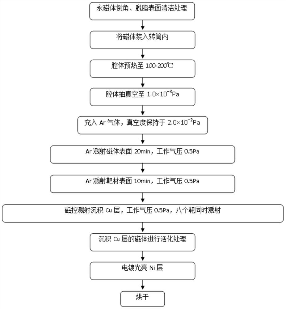
[0038] The present invention also provides a method for preparing a protective coating on the surface of an ultra-thin NdFeB permanent magnet, comprising the following steps:

[0039] 1) The surface-cleaned NdFeB magnet is subjected to DC magnetron sputtering coating to obtain a NdFeB magnet with Cu-Sn / Cu gradient coating deposited on the surface;

[0040] 2) The NdFeB magnet with a copper layer deposited on the surface is obtained by the above steps, and then the surface is pretreated, and then a nickel-based coating is applied to obtain a NdFeB magnet with a Cu-Ni composite coating deposited on the surface.

[0041] In the above-mentioned steps of the present invention, the selection principles and preferred ranges of the raw materials and structures used, if not specified, correspond to the selection principles and preferred ranges of the raw materials and structures in the aforementioned NdFeB magnets whose surface is coated with a Cu-Ni composite coating , which will not ...

Embodiment 1

[0055] 1) Soak the NdFeB magnet in a degreasing agent solution for 15 minutes, ultrasonically clean it for 1 minute, rinse it twice with clean water without removing the surface dirt, and place it on the workpiece bracket after drying;

[0056] 2) Turn on the heating device to keep the chamber temperature at 150°C, and at the same time turn on the vacuum pump to stabilize the vacuum degree of the chamber at 1.0×10⁻³Pa;

[0057] 3) Argon is used as the cleaning gas to remove oxides on the surface of the magnet and the surface of the target by sputtering;

[0058] 4) Turn on the ion source power supply, magnetron sputtering on the surface of the magnet, Cu-Sn / Cu gradient coating, the sputtering time is 1.5h, and the coating thickness is 5μm;

[0059] 5) activating the permanent magnet on which the copper layer was deposited using a dilute sulfuric acid solution with a concentration of 0.5 wt%, for 5 s;

[0060] 6) Plating bright nickel on the surface of the above-mentioned perm...

Embodiment 2

[0063] 1) Soak the NdFeB magnet in a degreasing agent solution for 15 minutes, ultrasonically clean it for 1 minute, rinse it twice with clean water without removing the surface dirt, and place it on the workpiece bracket after drying;

[0064] 2) Turn on the heating device to keep the chamber temperature at 150°C, and at the same time turn on the vacuum pump to stabilize the vacuum degree of the chamber at 1.0×10⁻³Pa;

[0065] 3) Argon is used as the cleaning gas to remove oxides on the surface of the magnet and the surface of the target by sputtering;

[0066] 4) Turn on the ion source power supply, magnetron sputtering on the surface of the magnet, Cu-Sn / Cu gradient coating, the sputtering time is 2.0h, and the coating thickness is 6.5μm;

[0067] 5) activating the permanent magnet on which the copper layer was deposited using a dilute sulfuric acid solution with a concentration of 0.5 wt%, for 5 s;

[0068] 6) Plating bright nickel on the surface of the above-mentioned pe...


PUM

PropertyMeasurementUnit
thicknessaaaaaaaaaa
thicknessaaaaaaaaaa
thicknessaaaaaaaaaa

Abstract

The invention discloses an ultra-thin permanent magnet with a coating deposited on the surface. The permanent magnet is a sheet with a thickness of ≤1 mm. 0-5.0% Nd, 0.5-2.5% B, 0-2.8% Al, 0-1.0% Cu, and the rest is Fe. Cu-Ni combined coating is deposited on the surface of the permanent magnet sheet. The Cu-Ni combined coating includes passing Copper-tin alloy sputtering layer deposited on the surface of permanent magnet flakes by sputtering, and a nickel-based protective layer deposited on the surface of copper-tin alloy sputtering layer by electroplating or electroless plating, copper-tin alloy sputtering layer, sputtering layer The tin content gradually decreases to zero from the bottom layer to the surface, and the surface layer is a pure copper layer, that is, the copper-tin alloy sputtering layer is a gradient coating. The ultra-thin permanent magnet combines the advantages of the magnetron sputtering process that does not require pickling pretreatment, and the prepared film layer is firmly deposited and dense and corrosion-resistant, and solves the problem of erosion of the matrix structure by pickling solution and electroplating solution during the surface treatment of the permanent magnet. A problem that causes a decrease in magnetic properties.

Description

technical field [0001] The invention relates to the technical field of an anti-corrosion coating on the surface of a permanent magnet material, in particular to an ultra-thin permanent magnet with a coating deposited on the surface. Background technique [0002] Rare-earth neodymium-iron-boron (NdFeB) permanent magnets with nickel plating have been widely accepted in the electronics industry. The nickel plating layer on the surface of the magnet generally adopts the Ni-Cu-Ni combination system, that is, the pre-plating nickel layer is used as the bottom layer to increase the bonding force of the plating layer, and then the copper plating layer and the bright nickel layer are applied to enhance its protective ability and achieve decorative properties. Require. The traditional electroplating nickel / copper / nickel surface treatment process is very mature for steel materials. However, due to the multi-phase structure and corrosion sensitivity of sintered NdFeB permanent magnet m...

Claims


Application Information

Patent Timeline
Patent Type & Authority Patents(China)
IPC IPC(8): C22C38/00C22C38/06C23C28/02H01F7/02H01F41/02
Inventor 高志强任鸿儒侯利锋卫英慧侯德琦
Owner TAIYUAN UNIV OF TECH
Learn More