
Underwater quenching method for thin steel plate

A thin steel plate, laser quenching technology, applied in furnaces, heat treatment equipment, heat treatment furnaces, etc., can solve the problem of limited heat transfer effect of water on the substrate

Active Publication Date: 2021-04-16
ZHEJIANG UNIV OF TECH
View PDF5 Cites 1 Cited by
  • Summary
  • Abstract
  • Description
  • Claims
  • Application Information

AI Technical Summary

Problems solved by technology

The above two methods rely on the heat conduction effect of water on the substrate, but in fact the upper surface of the laser quenching processing area is not in direct contact with the cooling water, and the heat transfer effect of water on the substrate is very limited

Method used


Image

  • Underwater quenching method for thin steel plate
  • Underwater quenching method for thin steel plate
  • Underwater quenching method for thin steel plate

Examples

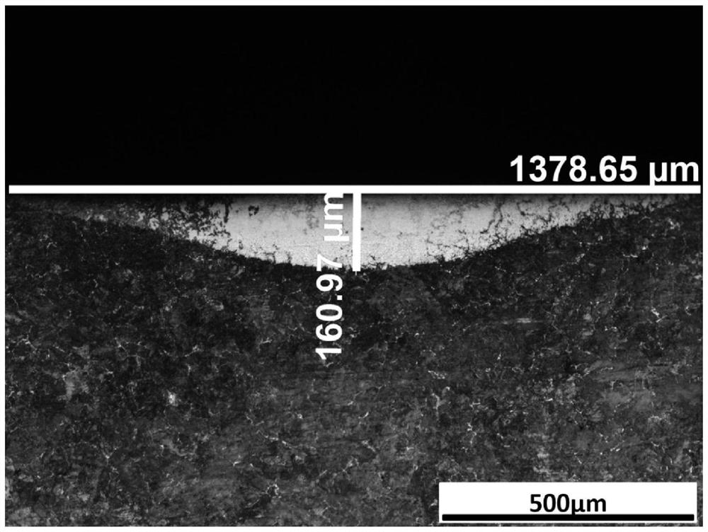

Embodiment 1

[0024] The base material used for underwater laser quenching is 45# steel, which is machined into a metal sample of 100×50×3mm. After the surface is degreased, derusted and polished, it is cleaned with anhydrous ethanol solution. Place two brackets at the bottom of the tank as supports, and place the metal sample on the brackets to avoid direct contact between the metal sample and the bottom of the tank. By adding an appropriate amount of deionized water into the water tank, the upper surface of the metal sample has a certain water layer thickness.

[0025] In this embodiment, the thickness of the water layer is controlled to be 2mm, the water flow direction is perpendicular to the laser scanning direction, the water flow velocity is 0.1m / s, the original water temperature is 20°C, and the side blowing device is placed horizontally. Adjust the laser power of the laser to 500W; the scanning speed to 2mm / s; the flow rate of the side blowing device to 50L / min; the spot size to 4mm...

Embodiment 2

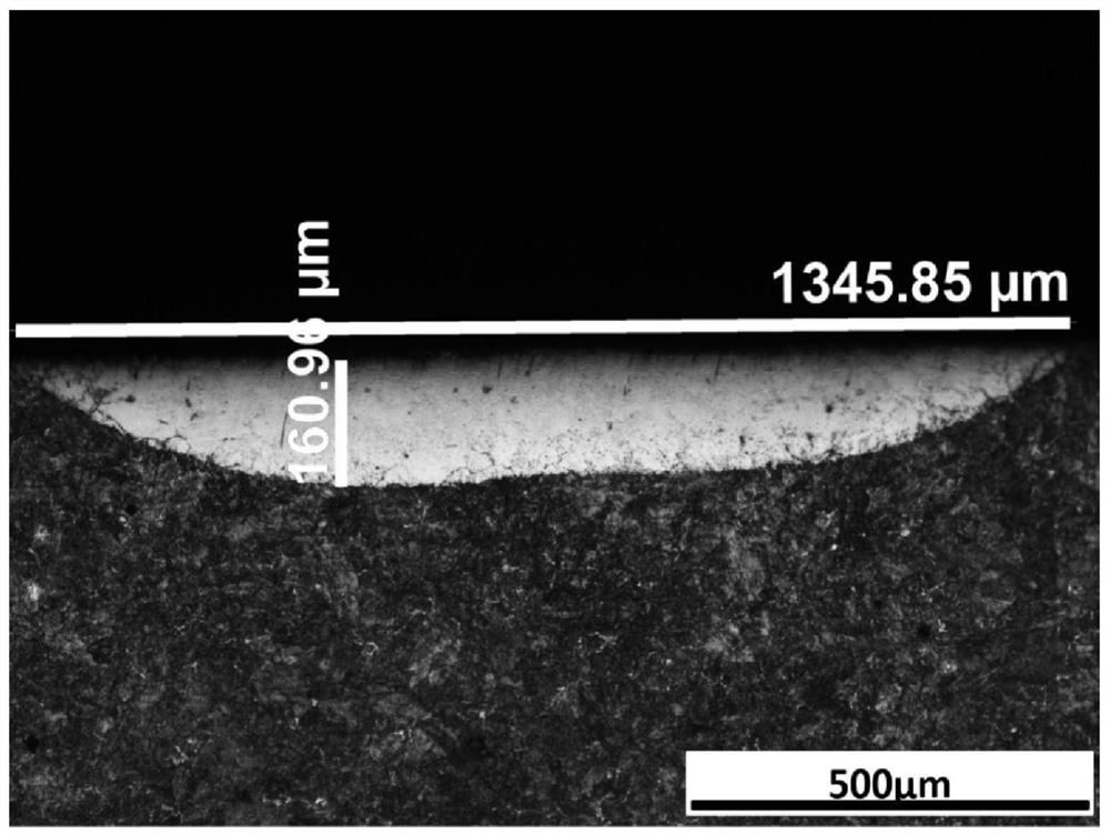
[0028] This embodiment raises the laser power in embodiment 1 to 800W, guarantees that other processing parameters are consistent with embodiment 1, obtains the sample hardened layer sectional view ( figure 2 shown), compare figure 1 It can be found that when the laser power increases, the quenched layer width and quenched layer depth increase significantly.

Embodiment 3

[0030] This example increases the water layer thickness in embodiment 2 to 8mm, guarantees that other processing parameters are consistent with embodiment 2, obtains the sample hardened layer sectional view ( image 3 shown), compare figure 2 It can be known that the thickness of the quenched layer and the width of the quenched layer are significantly reduced when the water layer is too thick.


PUM


Abstract

The invention discloses an underwater quenching method for a thin steel plate. The method comprises the following steps: polishing, cleaning and decontaminating the surface of a matrix; and standing the pretreated matrix in a water tank, completely immersing the upper surface of the matrix in water, scanning the surface of the matrix by using a blue / green laser with the wavelength range of 400-600nm, and meanwhile, adding a side blowing device to blow away water vapor generated in the laser quenching process in time. According to the method, the laser penetrates through a water layer to irradiate the upper surface of the steel plate, the temperature of the thin steel plate is rapidly increased to increase the surface temperature of the material to be the austenite transformation temperature or above, heat of the machined position of the surface of the thin steel plate is absorbed by the water layer on the upper surface of the thin steel plate, and cooling water absorbs heat to be severely vaporized to take away a large amount of heat, then, the thin steel plate is rapidly cooled, accordingly, the requirement for the hard outside and tough inside of the thin steel plate is met, and the thermal influence on the matrix part is reduced.

Description

technical field [0001] The invention relates to an underwater quenching method for thin steel plates. Background technique [0002] Laser phase transformation hardening is the most widely used technology in laser heat treatment. Its principle is to irradiate the surface of the material with a laser beam to increase the surface temperature of the material to a temperature range above the austenite transformation temperature and below the melting point. When irradiating the part, due to the effect of heat conduction, the matrix in the cold state makes the irradiated part rapidly cool down and undergo self-cooling and quenching, so as to obtain a finer hardened layer structure and realize the phase transformation hardening of the surface layer of the material. The self-cooling of workpiece parts depends on the heat conduction of the matrix part, but for thin-walled parts, the matrix part is thinner and less, and it often hardens or even melts through the steel plate during lase...

Claims


Application Information

Patent Timeline
IPC IPC(8): C21D9/46C21D1/09
Inventor 王梁贺定坤姚建华张群莉
Owner ZHEJIANG UNIV OF TECH
Learn More