
Injection locking method for satellite-borne high-energy narrow-pulse-width single-frequency laser

An injection-locking, high-energy technology, applied in the field of lasers, to achieve strong anti-interference ability, reduce jitter, and reduce time error effects

Active Publication Date: 2021-04-09
BEIJING RES INST OF TELEMETRY +1
View PDF10 Cites 0 Cited by
  • Summary
  • Abstract
  • Description
  • Claims
  • Application Information

AI Technical Summary

Problems solved by technology

[0005] The present invention aims to solve the problem that space lasers output high-stability, high-energy single-frequency pulse lasers in harsh environments, and provides a new injection locking method. The locking controller predicts the peak value of the resonance signal according to the resonance signal fed back by the photodetector. , and give the synchronous signal of the amplifier power supply and the trigger signal of the Q switch, and the output energy stability is better than 0.5% of the high-energy single-frequency pulse laser of the order of 100 millijoules

Method used


Image

  • Injection locking method for satellite-borne high-energy narrow-pulse-width single-frequency laser
  • Injection locking method for satellite-borne high-energy narrow-pulse-width single-frequency laser
  • Injection locking method for satellite-borne high-energy narrow-pulse-width single-frequency laser

Examples


Embodiment 1

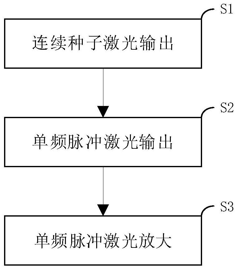
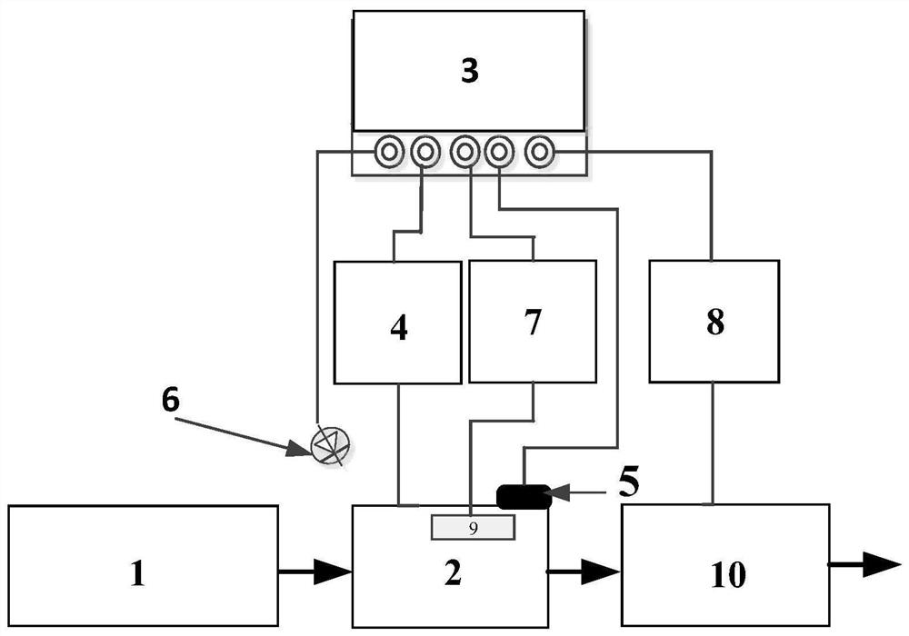
[0033] Such as Figure 1-2 As shown, an injection locking method for a spaceborne high-energy narrow-pulse width single-frequency laser is characterized in that: comprising the following steps:

[0034] S1. Continuous seed laser output: the seed laser 1 outputs the seed laser to the oscillator 2, the injection lock controller 3 outputs the synchronization signal to the oscillator power supply 4, and the oscillator power supply 4 starts to supply power to the oscillator 2;

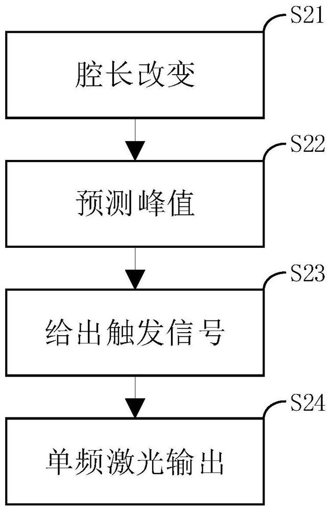
[0035] S2. Single-frequency pulse laser output: the injection lock controller 3 outputs a triangular wave voltage to control the reciprocating motion of the piezoelectric ceramic 5, the oscillator 2 changes the cavity length during the movement of the piezoelectric ceramic 5, and the photodetector 6 detects the oscillator 2 The resonant signal is fed back to the injection-locked controller 3, and the injection-locked controller 3 judges the peak value of the resonant signal and predicts the moment when the ...

Embodiment 2

[0038] Such as Figure 1-2 As shown, an injection locking method for a spaceborne high-energy narrow-pulse width single-frequency laser is characterized in that: comprising the following steps:

[0039] S1. Continuous seed laser output: seed laser 1 outputs 1064nm single-frequency continuous laser of fundamental transverse mode and single longitudinal mode as seed laser to oscillator 2, injection locking controller 3 outputs synchronization signal to oscillator power supply 4, oscillator power supply 4 Start powering Oscillator 2;

[0040] S2. Single-frequency pulse laser output: the injection lock controller 3 outputs a triangular wave voltage to control the reciprocating motion of the piezoelectric ceramic 5, the oscillator 2 changes the cavity length during the movement of the piezoelectric ceramic 5, and the photodetector 6 detects the oscillator 2 The resonant signal is fed back to the injection-locked controller 3, and the injection-locked controller 3 judges the peak v...


PUM


Abstract

The invention provides an injection locking method for a satellite-borne large-energy narrow-pulse-width single-frequency laser. The method comprises the steps: employing a pulse pumping and seed injection locking technology, enabling an injection locking controller to predict a resonance signal peak value according to a resonance signal fed back by a photoelectric detector, and giving an amplifier power synchronization signal and a Q-switch triggering signal; and reducing a time error of opening a Q switch, and decreasing the jitter of energy output. According to the invention, a problem of high-stability frequency locking of a satellite-borne nanosecond narrow-pulse-width laser is solved, and high-energy single-frequency pulse laser output with a stronger anti-interference capability and better energy stability can be realized.

Description

technical field [0001] The invention relates to the technical field of lasers, in particular to an injection locking method for a spaceborne high-energy narrow-pulse-width single-frequency laser. Background technique [0002] Space-borne direct wind measurement lidar and space-borne hyperspectral lidar can detect global three-dimensional wind field and cloud-aerosol, which is of great significance for accurate weather forecast and battlefield environment protection. Both space-borne direct wind measurement lidar and space-borne hyperspectral lidar require the laser used to be a single-frequency pulse laser, and at the same time require the laser to output a laser with a high energy stability of the order of 100 millijoules. [0003] There are two main technical methods to realize single-frequency pulsed laser: seed injection locking technology and seed chopper amplification technology. The seed injection locking technology is to inject a single-frequency, continuous seed li...

Claims


Application Information

Patent Timeline
Patent Type & Authority Applications(China)
IPC IPC(8): H01S3/094H01S3/098
CPCH01S3/1109H01S3/094076
Inventor 赵一鸣叶青李静周永升姜国庆于勇李凉海高明伟
Owner BEIJING RES INST OF TELEMETRY
Learn More