
Dynamic bending adjusting device and dynamic stable micron focusing system

An adjustment device and dynamic technology, applied in the application of diffraction/refraction/reflection for processing, nuclear engineering, radiation/particle processing, etc., can solve the problems of large spatial distance of focusing optical system, insufficient to meet application requirements, etc., and achieve optimal structure. , the effect of improving stability, high stability and uniformity

Active Publication Date: 2021-04-09
SHANGHAI INST OF APPLIED PHYSICS - CHINESE ACAD OF SCI +1
View PDF7 Cites 0 Cited by
  • Summary
  • Abstract
  • Description
  • Claims
  • Application Information

AI Technical Summary

Problems solved by technology

However, due to the large spatial distance of the focusing optical system, spatial stability is very important; in addition, to meet the needs of micro-nano spatial resolution, the grazing incidence mirror needs to be able to adjust the focus spot size to adapt to different samples and methods, and to achieve different scientific experiment purposes. Traditional fixed surface mirrors are no longer adequate for this application

Method used


Image

  • Dynamic bending adjusting device and dynamic stable micron focusing system
  • Dynamic bending adjusting device and dynamic stable micron focusing system
  • Dynamic bending adjusting device and dynamic stable micron focusing system

Examples


Embodiment 1

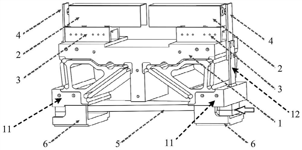
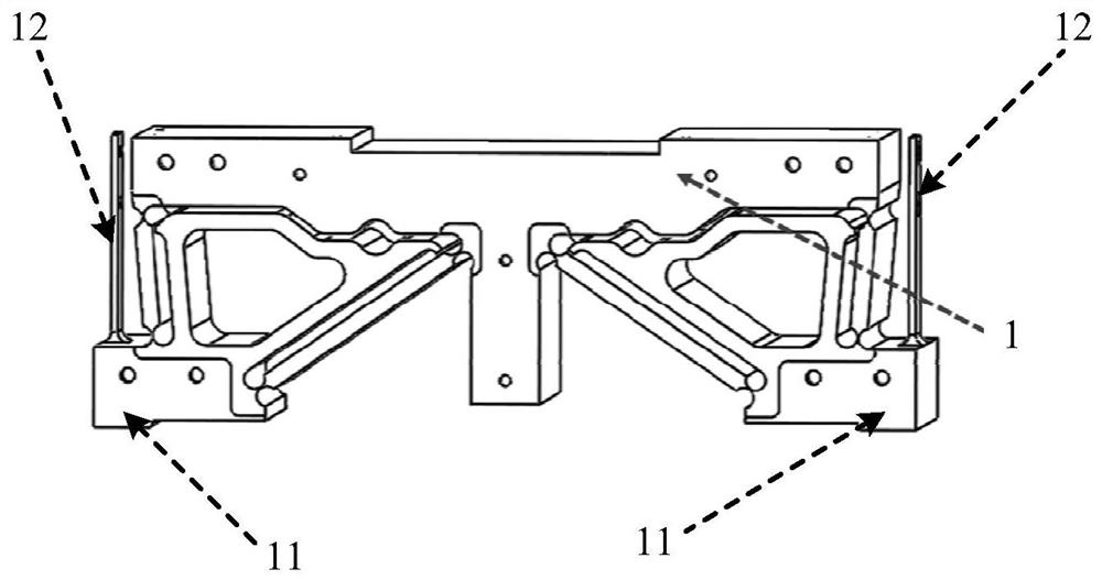
[0036] Such as figure 1 As shown, the embodiment of the present invention provides a dynamic bending adjustment device, which is basically an axisymmetric structure, including a compliance mechanism 1, two micro-displacement drivers 2, two support frames 3, two connectors 4, and two reflectors. Mirror holder 6 and grazing incidence mirror 5. Wherein the bottom of the compliance mechanism 1 is provided with two mounts 11, such as figure 2 As shown, they are respectively located on both sides of the bottom of the compliance mechanism 1. Each mounting base 11 is provided with an adjustment plate 12, and the adjustment plate 12 extends vertically upward from the upper surface of the installation base 11; On the opposite sides of the top of the mechanism 1, the two connecting pieces 4 are respectively connected to the free ends of the two adjustment plates 12 by screws, and extend in a direction vertical and away from the mounting base 11, and the two micro-displacement drivers 2...

Embodiment 2

[0047] This embodiment provides a dynamic and stable micro-focusing system, which includes a plurality of dynamic bending adjustment devices described in Embodiment 1, and a plurality of dynamic bending adjustment devices are combined to form a Kirkpatrick-Baez type optical focusing system, Montel Type optical focusing system or Wolter type focusing optical system.

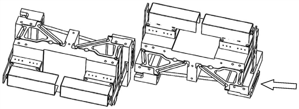
[0048] Such as image 3 As shown, it is a Kirkpatrick-Baez focusing optical system composed of two dynamic bending adjustment devices, where the two dynamic bending adjustment devices are arranged in front and back and are orthogonal to each other. During use, the grazing incident light along the direction of the arrow is reflected and focused into a line by the grazing incidence mirror of the first dynamic bending adjustment device, and then is second-time by the grazing incidence mirror of the second dynamic bending adjustment device The reflection is focused to a point, achieving two-dimensional focusing.

[...


PUM


Abstract

The invention relates to a dynamic bending adjusting device and a dynamic stable micron focusing system. The dynamic bending adjusting device comprises a compliant mechanism supported on two mounting seats at the bottom of the compliant mechanism, wherein adjusting plates vertically extend upwards and are arranged on the upper surfaces of the mounting seats, two supporting frames are fixed to the two sides of the top of the compliant mechanism correspondingly, the two connecting pieces are respectively connected with the free ends of the adjusting plates and extend along the surfaces vertical to and far away from the mounting seats, two micro-displacement drivers are respectively fixed on the two supporting frames, the side walls of the two micro-displacement drivers are respectively contacted with the two connecting pieces, the two reflector clamping pieces are respectively fixed on the bottom surfaces of the two mounting seats, and two ends of a grazing incidence reflector are respectively clamped between the reflector clamping pieces and the mounting seats. According to the dynamic bending adjusting device and the dynamic stable micron focusing system, the flexible mechanism is used for applying the bending moment with the tunable magnitude to the two ends of the grazing incidence reflector, so that the curvature radius of the reflector is adjusted in real time, dynamic micron focusing is achieved, and the stability of the size and position of a focusing light spot is improved.

Description

technical field [0001] The invention relates to synchrotron radiation beamline transmission and regulation technology, and more specifically to a dynamic bending adjustment device and a dynamic stable micron focusing system. Background technique [0002] Grazing incidence mirrors are widely used in the deflection and focusing of X-ray beamlines in the field of modern optical technology, especially on the beamlines of synchrotron radiation sources in large scientific installations. Commonly used mirror focusing modes include toric focusing and ellipsoidal focusing and parabolic focusing etc. However, due to the large spatial distance of the focusing optical system, spatial stability is very important; in addition, to meet the needs of micro-nano spatial resolution, the grazing incidence mirror needs to be able to adjust the focus spot size to adapt to different samples and methods, and to achieve different scientific experiment purposes. Traditional fixed surface mirrors are...

Claims


Application Information

Patent Timeline
Patent Type & Authority Applications(China)
IPC IPC(8): G21K1/06
CPCG21K1/067
Inventor 刘孟廷蒋力李中亮董晓浩李志军王劼
Owner SHANGHAI INST OF APPLIED PHYSICS - CHINESE ACAD OF SCI
Learn More