
Saw blade tooth end steel inlaying equipment for hardware tool machining

A technology of hardware tools and saw blades, which is applied in the field of steel-inlaid equipment for saw blade tooth ends used in hardware tool processing, and can solve problems such as difficult fixation, difficulty in inlaying steel work, unbearable human body, etc.

Pending Publication Date: 2021-04-09
晋江盾研机械设计有限公司
View PDF0 Cites 0 Cited by
  • Summary
  • Abstract
  • Description
  • Claims
  • Application Information

AI Technical Summary

Problems solved by technology

[0004] In order to overcome the shortcoming that the saw blade is relatively sharp and it is not easy to fix it, the temperature is too high when the welding torch is used manually, and the human body cannot bear it, so it is difficult to perform the work of inserting steel. Technical problem: provide a saw blade that can be fixed, Saw blade tooth end steel inlay equipment for metal tool processing without manual use of welding torch

Method used


Image

  • Saw blade tooth end steel inlaying equipment for hardware tool machining
  • Saw blade tooth end steel inlaying equipment for hardware tool machining
  • Saw blade tooth end steel inlaying equipment for hardware tool machining

Examples


Embodiment 1

[0068] A saw blade tooth end steel inlaid equipment for hardware tool processing, such as figure 1 As shown, it includes a mounting frame 1, a mounting plate 2, a cylinder 3, a fixing mechanism 4 and a cogging mechanism 5. The top of the mounting frame 1 is provided with a mounting plate 2, the bottom of the mounting frame 1 is provided with a cylinder 3, and the right side of the mounting frame 1 is provided with a There is a fixing mechanism 4, and the right side of the top of the mounting plate 2 is provided with an inlay mechanism 5.

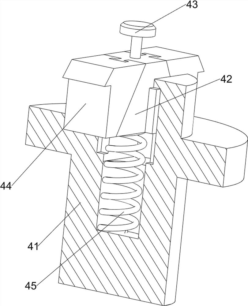
[0069] like figure 2 and image 3 As shown, the fixing mechanism 4 includes a fixing rod 40, a rotating shaft 41, a first inclined block 42, a clamping button 43, a first clamping block 44 and a first spring member 45, and the right side of the mounting frame 1 is provided with a fixing rod 40, which is fixed Bar 40 right side rotation type is provided with rotating shaft 41, and the sliding type in rotating shaft 41 is provided with the ...

Embodiment 2

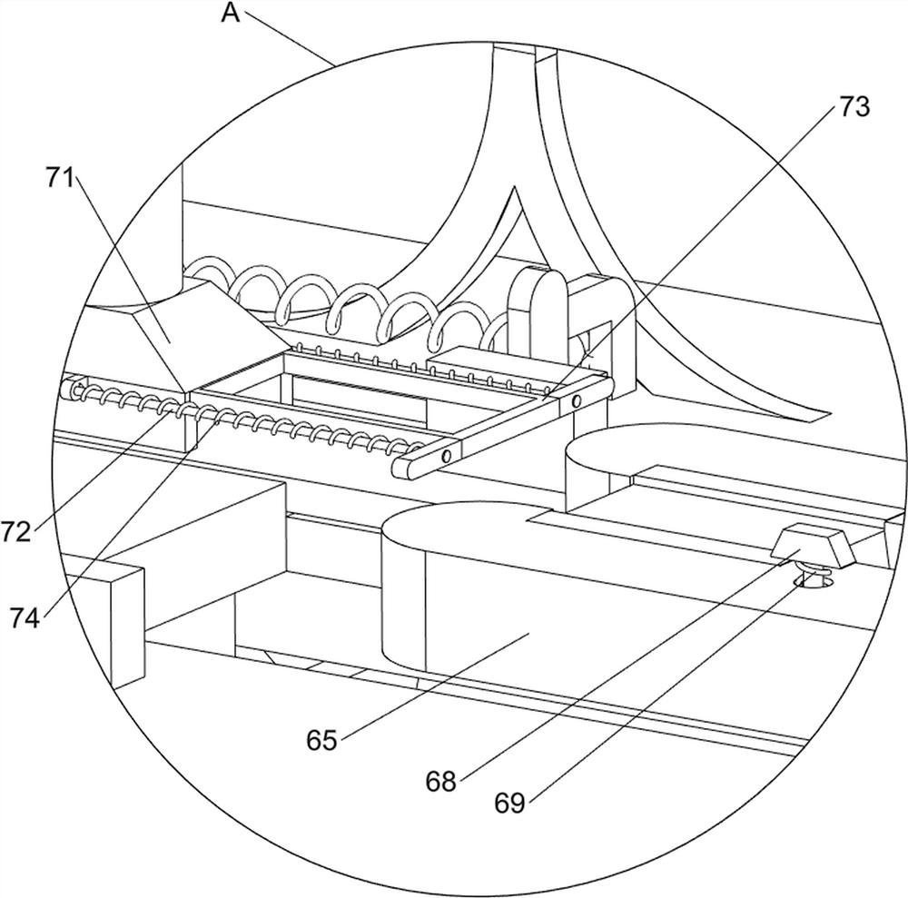
[0073] On the basis of Example 1, such as Figure 5 As shown, a tooth feeding mechanism 6 is also included, and the tooth feeding mechanism 6 includes a connecting frame 60, a first sliding block 61, a second inclined block 62, a third spring member 63, a second sliding block 64, and a second clamping block 65 , the fourth spring part 66, the second rocker 67, the third inclined block 68, the fifth spring part 69, the second stopper 610, the mounting block 611 and the sixth spring part 612, and the telescopic rod of the cylinder 3 is connected with the connecting frame 60 , the left side of the connecting frame 60 is provided with a first slider 61, the first slider 61 is slidably matched with the installation frame 1, and the first slider 61 is slidably provided with a second slanted block 62, and the second slanted block 62 is connected to the first slanted block 62. Two third spring members 63 are connected between one slide block 61, and a second slide block 64 is slidably...


PUM


Abstract

The invention relates to steel inlaying equipment, in particular to saw blade tooth end steel inlaying equipment for hardware tool machining. According to the saw blade tooth end steel inlaying equipment for hardware tool machining, a saw blade can be fixed, and a welding gun does not need to be manually used for steel inlaying work. According to the technical scheme, the saw blade tooth end steel inlaying equipment for hardware tool machining comprises an installation frame which is provided with an installation plate at the top, an air cylinder which is arranged at the bottom of the installation frame, a fixing mechanism which is arranged at one side of the installation frame, and a tooth inlaying mechanism which is arranged at one side of the top of the installation plate. The saw blade to be subjected to steel inlaying can be fixed through the arranged fixing mechanism; and the steel inlaying work can be carried out on the saw blade through the arranged tooth inlaying mechanism.

Description

technical field [0001] The invention relates to a steel-inserting device, in particular to a steel-inserting device for saw blade tooth ends used for processing hardware tools. Background technique [0002] Saw blades are a general term for thin circular knives used to cut solid materials. Saw blades can be divided into: diamond saw blades for stone cutting; high-speed steel saw blades for metal material cutting; solid wood, furniture, wood-based panels , aluminum alloy, aluminum profile, radiator, plastic and plastic steel cutting carbide saw blade, in the process of using the saw blade, in order to prolong its service life, steel will be inlaid on the tooth end, which is currently done manually This work, but the saw blade is relatively sharp, and it is not easy to fix it. The temperature is too high when the welding torch is used manually, and the human body cannot bear it, so it is difficult to carry out the steel inlaid work. [0003] Therefore need to design a kind of...

Claims


Application Information

Patent Timeline
IPC IPC(8): B23P5/00
CPCB23P5/00
Inventor 朱仁英
Owner 晋江盾研机械设计有限公司
Learn More