Equipment for glazing ceramic cups
A technology for ceramic cups and equipment, applied in ceramic molding machines, manufacturing tools, etc., can solve the problem of uneven glazing on the surface of ceramic cups
- Summary
- Abstract
- Description
- Claims
- Application Information
AI Technical Summary
Problems solved by technology
Method used
Image
Examples
Embodiment 1
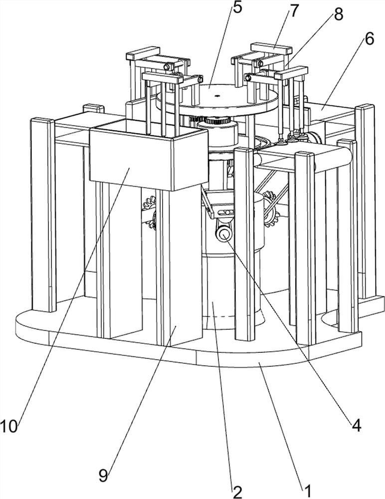
[0024] A kind of equipment for glazing ceramic cups, such as figure 1 and figure 2 As shown, it includes a base 1, a fixed seat 2, a servo motor 3, a lifting mechanism 4, a rotating mechanism 5, a feeding and discharging mechanism 6, a bracket 7, an electric suction cup 8, a second support plate 9 and a glaze pool 10, and the middle of the top of the base 1 There is a fixed seat 2, the bottom of the inner wall of the fixed seat 2 is connected with a servo motor 3, the top of the fixed seat 2 is connected with a lifting mechanism 4, the parts of the lifting mechanism 4 are connected with the output shaft of the servo motor 3, and the top of the parts of the lifting mechanism 4 is provided with a rotating Mechanism 5, the top of the base 1 is provided with a feeding and discharging mechanism 6, the parts of the feeding and discharging mechanism 6 are connected with the fixed seat 2, and the top of the rotating mechanism 5 is evenly provided with brackets 7 in the circumferentia...
Embodiment 2
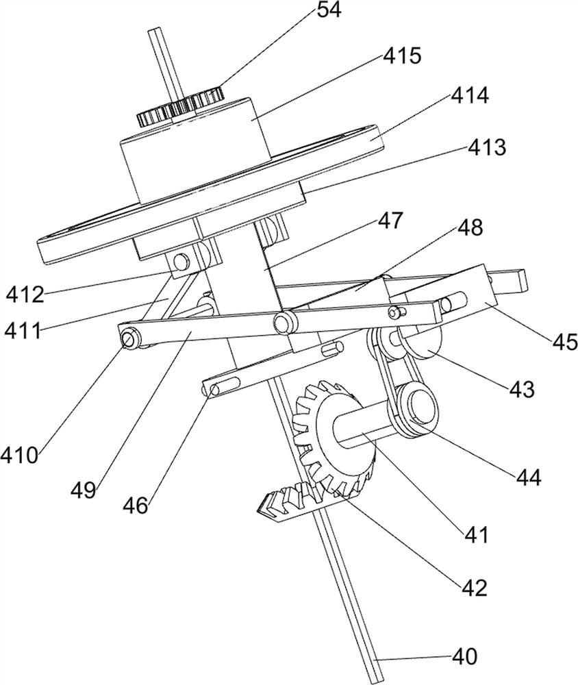
[0027] On the basis of Example 1, such as image 3 and Figure 4 As shown, the lifting mechanism 4 includes a first rotating rod 40, a first rotating shaft 41, a first bevel gear set 42, a first rotating block 43, a first pulley assembly 44, a pushing block 45, a first support plate 46, a sleeve Rod 47, supporting block 48, second rotating block 49, connecting shaft 410, connecting block 411, fixed block 412, connecting plate 413, first bearing block 414 and sleeve 415, the output shaft of servo motor 3 is connected with the first rotating block. Rod 40, the top right front side of the fixed seat 2 is rotationally connected with the first rotating shaft 41, the first bevel gear set 42 is connected between the first rotating shaft 41 and the first rotating rod 40, and the right front side of the top of the fixed seat 2 is provided with a support Block 48, the second rotating block 49 is connected with the rotating type between the left and right sides of the support block 48 t...
Embodiment 3
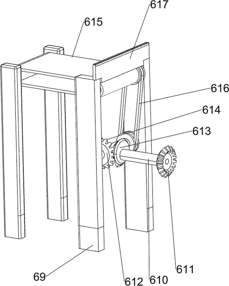
[0032] On the basis of Example 2, such as figure 2 , Figure 5 , Figure 6 and Figure 7 As shown, the feeding and discharging mechanism 6 includes a second support rod 60, a second rotating shaft 61, a second bevel gear 62, a third rotating rod 63, a first missing gear 64, a third bevel gear 65, and a first conveyor belt assembly 66. , the second pulley assembly 67, the first baffle plate 68, the third support rod 69, the third rotating shaft 610, the fourth bevel gear 611, the fourth rotating rod 612, the second missing gear 613, the fifth bevel gear 614, the second Two conveyor belt assemblies 615, the third pulley assembly 616 and the second baffle plate 617, the left side of the top of the base 1 is evenly provided with the second support rods 60, the number of the second support rods 60 is 4, and the tops of the second support rods 60 rotate The first conveyor belt assembly 66 is connected with the first conveyor belt assembly 66, the left side of the upper part of t...
PUM
 Abstract
Description
Claims
Application Information
 - R&D
- Intellectual Property
- Life Sciences
- Materials
- Tech Scout
- Unparalleled Data Quality
- Higher Quality Content
- 60% Fewer Hallucinations
Browse by: Latest US Patents, China's latest patents, Technical Efficacy Thesaurus, Application Domain, Technology Topic, Popular Technical Reports.
© 2025 PatSnap. All rights reserved.Legal|Privacy policy|Modern Slavery Act Transparency Statement|Sitemap|About US| Contact US: help@patsnap.com


