Iron ore powder liquid phase fluidity detection method based on sintering actual production conditions

A liquid phase fluidity and detection method technology, which is applied in the field of ironmaking and sintering, can solve the problems of matching, increasing the effective contact area, liquid phase generation and flow ductility interference, etc., and achieves low test cost, easy operation, and equipment simple effect

Active Publication Date: 2021-04-06
NORTH CHINA UNIVERSITY OF SCIENCE AND TECHNOLOGY +1
View PDF7 Cites 0 Cited by
  • Summary
  • Abstract
  • Description
  • Claims
  • Application Information

AI Technical Summary

Problems solved by technology

[0004] However, the above detection methods do not fully consider the actual sintering production situation, and all have the following disadvantages: First, in the actual sintering production, the sintering ore blending is based on the balanced SiO2. The actual control level is also different, but under the premise that the SiO2 control is relatively stable, the binary alkalinity of the sintered finished ore is generally controlled between 2.0-2.2, and the CaO mass fraction is also basically stable at a certain level. Using a fixed binary alkalinity of 4.0 as the basis for the determination of the liquid phase fluidity of a single iron ore powder, artificial factors have increased the effective component of CaO in iron ore powder; the second is that calcium ash is used as a flux in sintering production, and CaO in calcium ash Mass fraction of 77%-80%, SiO2 mass fraction of 3.5%-4.5%, and MgO mass fraction of 1.5%-2.0%, the SiO2 and MgO components will interfere with t

Method used


Image

  • Iron ore powder liquid phase fluidity detection method based on sintering actual production conditions
  • Iron ore powder liquid phase fluidity detection method based on sintering actual production conditions
  • Iron ore powder liquid phase fluidity detection method based on sintering actual production conditions

Examples


Embodiment

[0023] The general idea and implementation steps of the embodiment are as follows:

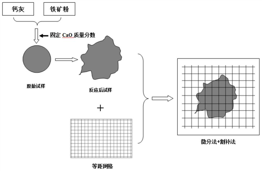
[0024] 1) Preliminary preparation: draw equidistant grid lines on the plexiglass plate, the present invention is a unit grid of 5 mm × 5 mm, and calculate the vertical projected area of ​​the sample after melting by using the differential method + cutting and complementing method.

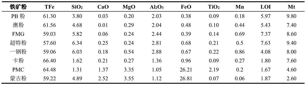
[0025] 2) Sample preparation: the present invention selects the calcium ash at the sintering production site as a flux, and dries the calcium ash and the iron ore powder sample to be tested at a temperature of 105° C. for 2 hours; the dried calcium ash and iron ore Grind the powder, pass through a -200 mesh process sieve, and take the under-sieve to test CaO and SiO 2 quality score.

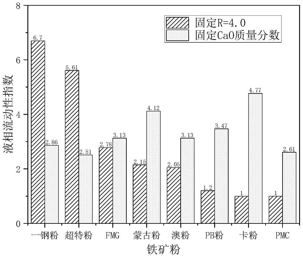
[0026] 3) Sample preparation: on the premise of the actual value of the CaO mass fraction in the sinter or a certain fixed value, set the CaO mass fraction in the mixture as a constant amount, and according to the calcium ash and iro...


PUM


Abstract

The invention discloses an iron ore powder liquid phase fluidity detection method based on sintering actual production conditions, and belongs to the technical field of ironmaking sintering. The method comprises the following steps: taking the actual industrial analysis CaO mass fraction of sinter as a constant target value; selecting calcium ash in a sintering production field as a flux, and determining that the mass fraction of CaO in a mixture is a batching structure with a set constant target value according to the mass fractions of the calcium ash, iron ore powder SiO2 and CaO; pressing a sample with a fixed specification by using a grinding tool, and simulating a sintering temperature rise curve to sinter the sample; utilizing organic glass with equidistant grids to calculate the vertical projection area of the fused sample by applying a differential method and a cutting compensation method; characterizing the ratio of the vertical projection area of the sample after melting to the vertical projection area of the sample before melting as a liquid phase fluidity index; taking an index mean value of a plurality of groups of samples of a single iron ore powder as the liquid phase fluidity of the iron ore powder under the actual sintering production condition, and guiding the sintering ore blending according to the complementation principle.

Description

technical field [0001] The invention belongs to the technical field of ironmaking and sintering, and relates to a detection method based on the liquid phase fluidity of iron ore powder under actual sintering production conditions. Background technique [0002] Sinter is the most important iron-containing raw material for blast furnaces in my country, and its quality is directly related to the straightness of the blast furnace and the technical and economic indicators. During the sinter production process, the iron ore powder is mixed with a certain proportion of materials such as flux, fuel, returned ore, and solid waste inside the iron and steel enterprise. At the sintering temperature, part of the mixture is melted and liquefied to form a liquid phase and spread around. Adhere to the surrounding fine powder particles, and form liquid phase consolidation under cooling to form sinter. If the fluidity of the sintering liquid phase is too large or too small, the strength of t...

Claims


Application Information

Patent Timeline
IPC IPC(8): G01N11/00G01N25/02G01B5/26C22B1/16
CPCG01N11/00G01N25/02G01B5/26C22B1/16Y02P10/20
Inventor 胡长庆师学峰韩伟刚龙跃李永生胡启辰韩涛赵凯王志星
Owner NORTH CHINA UNIVERSITY OF SCIENCE AND TECHNOLOGY
Why Eureka
Try Eureka