Nozzle, hard pipe joint structure, and device and method for nipple processing
A joint structure, hard pipe technology, applied in the direction of pipe/pipe joint/pipe fitting, manufacturing tool, sleeve/socket connection, etc., can solve the problem of difficult application of hydraulic system, etc., and achieve the effect of high pressure level and reliable sealing
- Summary
- Abstract
- Description
- Claims
- Application Information
AI Technical Summary
Problems solved by technology
Method used
Image

Examples
Embodiment 1
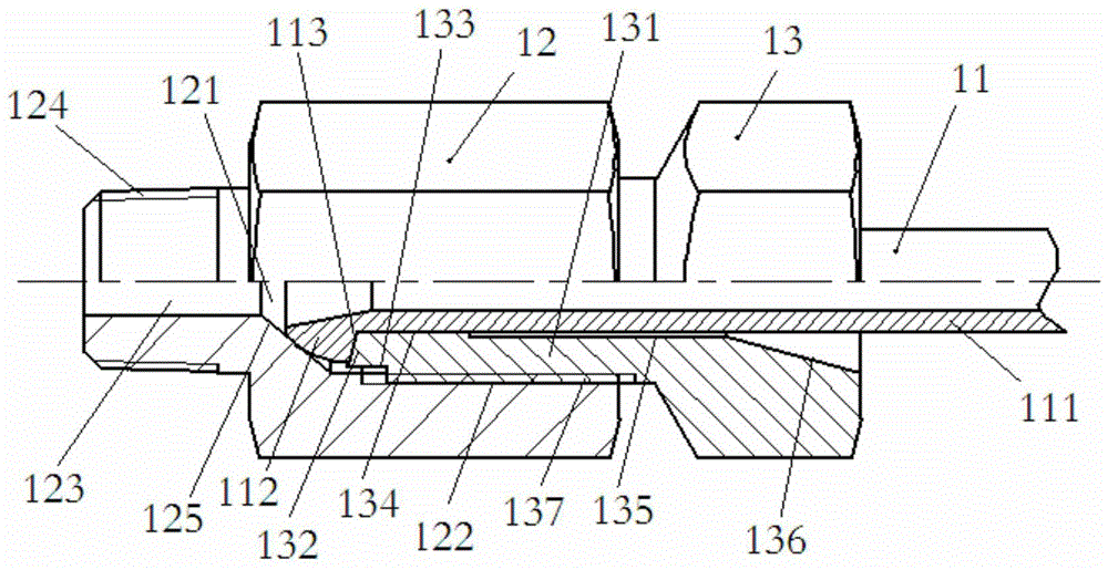
[0035] Please refer to figure 1 , the first embodiment provides a hard pipe joint structure, which includes a connecting pipe 11 , a joint body 12 and a connecting piece 13 .
[0036] The connecting pipe 11 has a through hole, which can be optionally annealed and treated with a low carbon steel seamless pipe. The connecting pipe 11 includes a pipe body 111 and a spherical head body 112 coupled with the pipe body 111 . The diameter of the bottom wall 113 of the head body 112 is larger than the diameter of the pipe body 111 , so that the head body 112 protrudes laterally from the outer wall of the pipe body 111 to form a root angle. The root angle can be any angle, and here are three examples, such as 90°, 115° or 135°, among which 115° and 135° are more conducive to stress, and avoid the problem of root cracks after multiple uses of the head body 112 .
[0037] The joint body 112 has a flow hole, and the flow hole is divided into a first hole section 121 , a second hole secti...
Embodiment 2
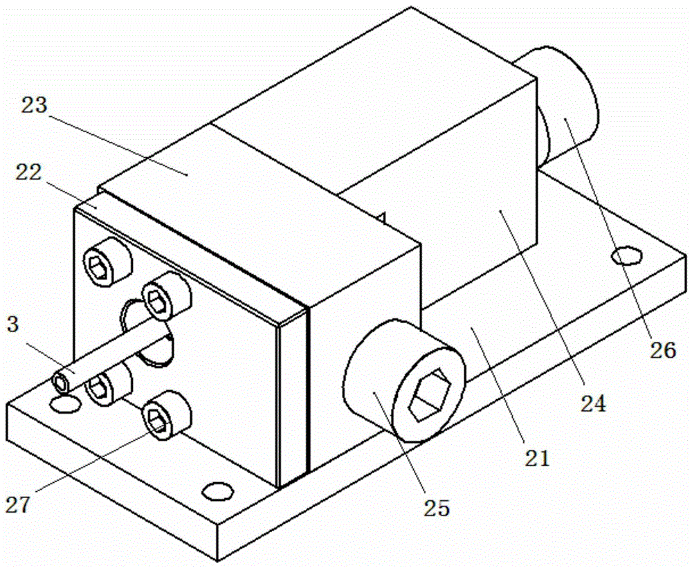
[0057] Please refer to figure 2 , the second embodiment provides a pipe connection processing device, which includes a base 21, an end cover plate 22, a pipe mold assembly 23, a ball mold assembly 24, a locking member 25 and a force member 26, which can be used to manufacture A nozzle shown and other nozzles having a spherical head.
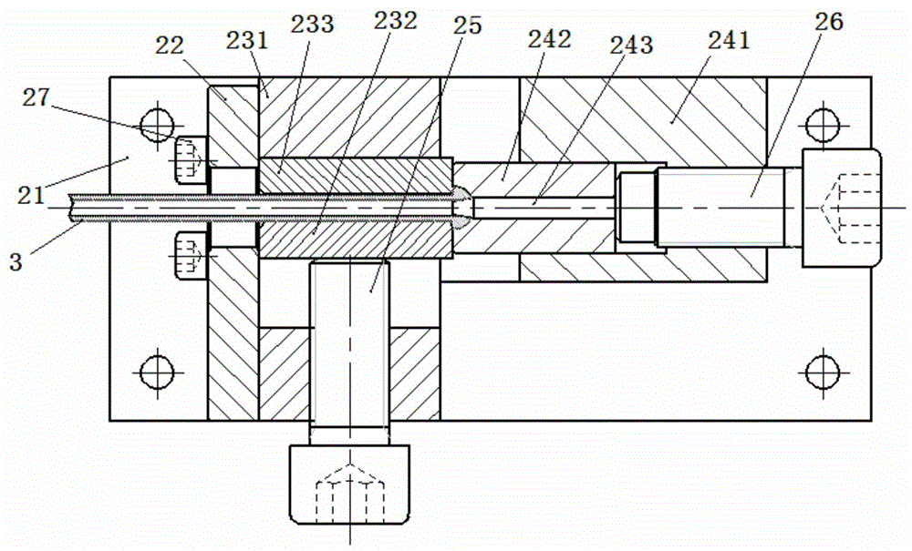
[0058] Specifically, please refer to image 3 , the base 21 is used to make the whole device, which can be fixed on any stable position (such as a simple workbench), and the end cover plate 22 is then fixed on the base 21 .
[0059] In this embodiment, the pipe mold assembly 23 has a pipe mold body 231 , a first pipe mold 232 and a second pipe mold 233 . The nozzle mold body 231 is fixed on the base 21 and one end is against the end cover plate 22 , or it can be further locked on the end cover plate 22 by locking screws.
[0060] In addition, in addition to using the end cover plate 22 to limit the position of the pipe mold body 231, a limiti...
Embodiment 3
[0077] The third embodiment provides a processing method for the connecting pipe, which is to use a cold rolling forming process to roll the head body of the connecting pipe into a spherical shape.
[0078] The device shown in Embodiment 2 is a device designed according to the method shown in Embodiment 3. Of course, the device shown in Embodiment 2 is only an example of this method, and this method can also be realized by other devices in actual operation. method.
PUM
 Abstract
Description
Claims
Application Information
 - R&D
- Intellectual Property
- Life Sciences
- Materials
- Tech Scout
- Unparalleled Data Quality
- Higher Quality Content
- 60% Fewer Hallucinations
Browse by: Latest US Patents, China's latest patents, Technical Efficacy Thesaurus, Application Domain, Technology Topic, Popular Technical Reports.
© 2025 PatSnap. All rights reserved.Legal|Privacy policy|Modern Slavery Act Transparency Statement|Sitemap|About US| Contact US: help@patsnap.com