
Aviation aluminum alloy minimal quantity lubrication milling device

A micro-lubrication and milling technology, used in metal processing equipment, metal processing mechanical parts, positioning devices, etc., can solve the problems of large movement space, unreliable clamping, high labor intensity, etc., to reduce manufacturing costs, clamping High reliability and the effect of reducing labor intensity

Active Publication Date: 2021-04-06
QINGDAO TECHNOLOGICAL UNIVERSITY +1
View PDF9 Cites 4 Cited by
  • Summary
  • Abstract
  • Description
  • Claims
  • Application Information

AI Technical Summary

Problems solved by technology

[0006] For the design of processing technology equipment and corresponding cooling and lubrication systems for large aviation aluminum alloy workpieces and similar workpieces, researchers have made great progress. At present, many designers have designed related fixtures and process equipment in related fields. It solves the problems in the processing of workpieces such as low positioning accuracy, high labor intensity, and low production efficiency. However, for large workpieces, due to the large size and weight of the workpiece, unreliable clamping is prone to occur during processing.
Moreover, there are many minimal quantity lubrication devices designed by designers, which have made outstanding contributions in terms of resource saving and lubrication performance. However, the compatibility with fixtures is low, and there is no good combination with the process equipment of fixtures.
The atomizing nozzle of the minimum quantity lubrication device is generally suspended on the side of the machine tool spindle, which requires a large movement space during processing
Moreover, due to the consideration of workpiece structure and workpiece clamping requirements, some parts of the fixture may be higher than the surface of the workpiece, so the nozzle is likely to interfere with the fixture, causing equipment damage

Method used


Image

  • Aviation aluminum alloy minimal quantity lubrication milling device
  • Aviation aluminum alloy minimal quantity lubrication milling device
  • Aviation aluminum alloy minimal quantity lubrication milling device

Examples


Embodiment Construction

[0099] It should be pointed out that the following detailed description is exemplary and intended to provide further explanation to the present application. Unless defined otherwise, all technical and scientific terms used herein have the same meaning as commonly understood by one of ordinary skill in the art to which this application belongs.

[0100] It should be noted that the terminology used here is only for describing specific implementations, and is not intended to limit the exemplary implementations according to the present application. As used herein, unless the context clearly dictates otherwise, the singular is intended to include the plural, and it should also be understood that when the terms "comprising" and / or "comprising" are used in this specification, they mean There are features, steps, operations, means, components and / or combinations thereof.

[0101] For the convenience of description, if the words "up", "down", "left" and "right" appear in the present i...


PUM


Abstract

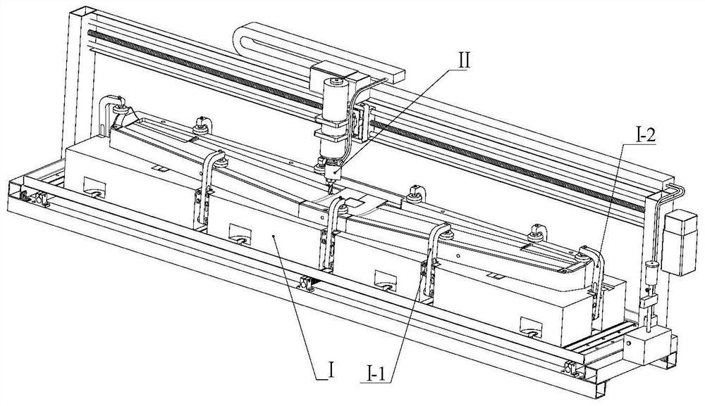
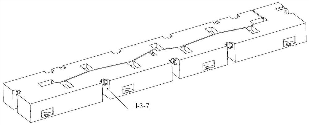
The invention relates to an aviation aluminum alloy minimal quantity lubrication milling device. The aviation aluminum alloy minimal quantity lubrication milling device comprises a machine tool workbench and a main shaft connected with a machine tool power system, wherein the main shaft is connected with a tool handle; the tool handle is fixed to a tool; the machine tool workbench is provided with a machine tool clamp; the tool handle is connected with a minimal quantity lubrication mechanism; the machine tool clamp comprises a clamp body; a limiting block is fixed to the clamp body and used for making contact with the two adjacent side faces of a workpiece; the clamp body is further provided with a plurality of clamping elements capable of pressing the workpiece to the upper surface of the clamp body; and a detection piece is arranged on the top of each clamping element and used for detecting the relative position of the clamping element and the main shaft. According to the device, interference touch of a nozzle and the clamping elements can be avoided.

Description

technical field [0001] The invention relates to the technical field of mechanical processing equipment, in particular to an aviation aluminum alloy micro-lubrication milling processing device. Background technique [0002] The statements herein merely provide background information related to the present invention and do not necessarily constitute prior art. [0003] Aluminum alloy has excellent casting performance, good plastic processing performance, good mechanical performance, good workability, good wear resistance, strong corrosion resistance, good oxidation resistance, etc., and is widely used in aerospace, mold processing, machinery Equipment, fixtures and other fields, especially for aerospace manufacturing and other high-stress structures that require high strength and strong corrosion resistance. When manufacturing some parts in the aerospace field, the corresponding molds for such parts are usually designed and processed first. The workpieces in the aerospace fi...

Claims


Application Information

Patent Timeline
Patent Type & Authority Applications(China)
IPC IPC(8): B23Q11/10B23Q3/06
CPCB23Q11/1046B23Q3/06B23C1/06B23C2222/04B23C2215/04B23Q3/069B23Q3/082B23Q17/003B23C9/00B23C2270/08B23Q11/10Y10T409/303976B23C1/002Y10T409/308288Y10T409/309016Y10T409/304032
Inventor 杨敏马浩李长河吴喜峰韩一学杨玉莹崔歆赵绪峰张乃庆吴启东高腾张彦彬卢秉恒刘明政贾东洲张效伟王晓铭
Owner QINGDAO TECHNOLOGICAL UNIVERSITY
Learn More