


Quick Research
Generate reliable direction feasibility study reports for your R&D in just a few steps.

Technical Q&A
Discover and master advanced knowledge NOW. Basics, ideas, possibilities, all at once.

Find Solutions
As an expert in R&D theories, this can generate solutions to your technical problems instantly.

Evaluate Feasibility
Analyze your overall solution with one click, know your potential R&D risks in advance.

Monitor Landscape
Get weekly tech updates, stay abreast of the latest tech innovations and key insights.
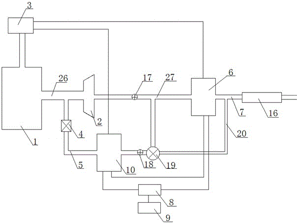
A two-stage linkage vehicle exhaust temperature difference power generation system
A technology of thermoelectric power generation and automobile exhaust, applied in the direction of generators/motors, electrical components, engine components, etc., can solve the problems of low power generation and conversion efficiency, unstable voltage/current output, etc., and achieve the effect of improving the overall power generation
- Summary
- Abstract
- Description
- Claims
- Application Information
AI Technical Summary
Problems solved by technology
Method used
Image

Examples
Embodiment 1
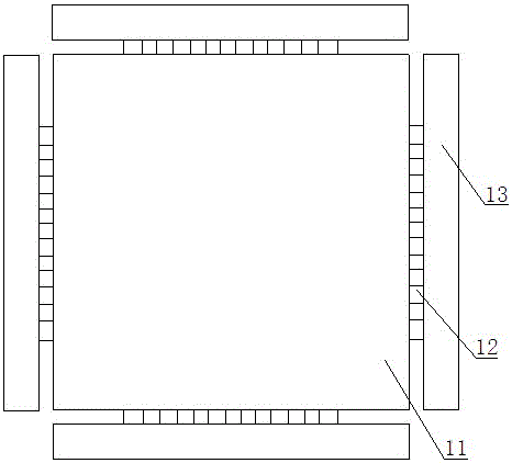
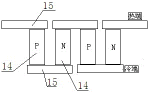
[0029] see figure 2 In this embodiment, the thermoelectric power generation device I6 or the thermoelectric power generation device II10, or the thermoelectric power generation device I6 and the thermoelectric power generation device II10 select the following thermoelectric power generation device at the same time, which includes a heat collecting gas tank 11, a power generation module 12 and a cooling water jacket 13, specifically Please refer to the content of the utility model patent "An Automobile Exhaust Temperature Difference Power Generation Device" filed by the applicant on the same day. The heat collecting end air box 11 is a masonry cylinder air box made of pure aluminum with a square cross section, the cooling end water jacket 13 is a flat cuboid made of pure aluminum, the hot end of the power generation module 12 and the heat collecting gas The outer surface of the box 1 is attached, and the cold end of the power generation module 2 is attached to the outer surfac...
Embodiment 2
[0035] see Figure 4 , see figure 2 , in the present embodiment, the thermoelectric power generation device I6 or the thermoelectric power generation device II10, or the thermoelectric power generation device I6 and the thermoelectric power generation device II10 select the following thermoelectric power generation device simultaneously, which includes a heat collector 21, a thermoelectric power generation sheet 22 and a plurality of masonry prisms Body 23, for details, please refer to the content of the utility model patent "A Vehicle Exhaust Temperature Difference Power Generation Device" filed by the applicant on the same day. The heat collector 21 includes a hollow box body and air inlets and air outlets at both ends, and the air inlet and the air outlet of the heat collector 21 are used as the air inlet and the air outlet of the thermoelectric power generation device to collect the exhaust heat, so The plurality of masonry prisms 23 are arranged inside the box body of t...
PUM
 Abstract
Description
Claims
Application Information
 - R&D Engineer
- R&D Manager
- IP Professional
- Industry Leading Data Capabilities
- Powerful AI technology
- Patent DNA Extraction
Browse by: Latest US Patents, China's latest patents, Technical Efficacy Thesaurus, Application Domain, Technology Topic, Popular Technical Reports.
© 2024 PatSnap. All rights reserved.Legal|Privacy policy|Modern Slavery Act Transparency Statement|Sitemap|About US| Contact US: help@patsnap.com