A belt-type suction sintering process with inclined downward sintering airflow
A kind of air flow and process technology, applied in the direction of furnace, furnace type, lighting and heating equipment, etc., to achieve the effect of improving quality, reducing material layer resistance, and reducing particle concentration
- Summary
- Abstract
- Description
- Claims
- Application Information
AI Technical Summary
Problems solved by technology
Method used
Image
Examples
Embodiment 1
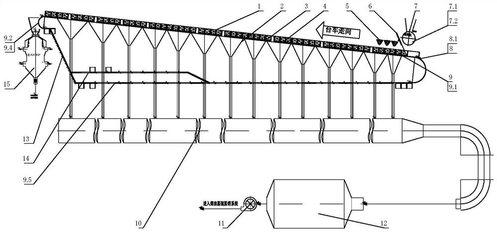
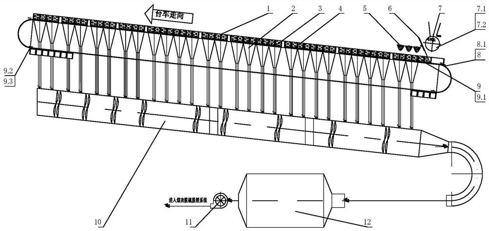
[0037] see figure 1 , including a sintering machine trolley 1, a sintering machine bellows 2 is arranged below the trolley 1, and the trolley 1 has a sintering material layer 3 and a bottoming material 4, and the sintering material layer 3 and the bottoming material 4 are placed with the trolley 1. Driven by the head transmission mechanism 8, the head star wheel 8.1 pushes the sintering head to run along the upper inclined track 9.1 of the sintering machine trolley track 9 to the tail of the machine, discharges the material at the fixed track 9.2 at the tail, and enters the lower layer Inclined track 9.3. The trolley 1 entering the lower inclined track 9.3 is pushed by the trolley 1 behind it, travels along the lower inclined track 9.3 to the sintering head, and is pushed into the upper inclined track 9.1 by the head star wheel 8.1. The trolley 1 entering the upper inclined track 9.1 travels below the distribution system 7, and the sintered mixture passes through the lowering...
Embodiment 2
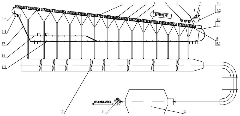
[0039] see figure 2 , including a sintering machine trolley 1, a sintering machine bellows 2 is arranged below the trolley 1, and the trolley 1 has a sintering material layer 3 and a bottoming material 4, and the sintering material layer 3 and the bottoming material 4 are placed with the trolley 1. Driven by the head drive mechanism 8, driven by the head star wheel 8.1, the sintering head runs along the upper inclined track 9.1 of the sintering machine trolley track 9 to the tail of the machine, unloads the material at the fixed track 9.2 at the tail, and enters the middle layer Orbit 9.4. The trolley 1 entering the middle track 9.4 moves forward on the chain belt 13 connecting the middle track 9.4 and the lower track 9.5 under the push of the trolley 1 behind it, and is pulled to the lower track 9.5 by the chain belt 13, along the lower track 9.5. Track 9.5 travels to the sintering head. The trolley 1 traveling to the sintering head along the lower track 9.5 is pushed by t...
Embodiment 3
[0041] see figure 2 , including a sintering machine trolley 1, a sintering machine bellows 2 is arranged below the trolley 1, and the trolley 1 has a sintering material layer 3 and a bottoming material 4, and the sintering material layer 3 and the bottoming material 4 are placed with the trolley 1. Driven by the head drive mechanism 8, driven by the head star wheel 8.1, the sintering head runs along the upper inclined track 9.1 of the sintering machine trolley track 9 to the tail of the machine, unloads the material at the fixed track 9.2 at the tail, and enters the middle layer Orbit 9.4. If the trolley 1 entering the middle track 9.4 needs to be repaired, it will be pulled to the trolley maintenance platform 14 by the push of the trolley 1 behind it and on the chain belt 13 for maintenance. The well-maintained trolley enters the lower track 9.5 through the track of the trolley inspection platform 14, and then travels to the sintering head. The trolley 1 traveling to the s...
PUM
 Abstract
Description
Claims
Application Information
 - R&D
- Intellectual Property
- Life Sciences
- Materials
- Tech Scout
- Unparalleled Data Quality
- Higher Quality Content
- 60% Fewer Hallucinations
Browse by: Latest US Patents, China's latest patents, Technical Efficacy Thesaurus, Application Domain, Technology Topic, Popular Technical Reports.
© 2025 PatSnap. All rights reserved.Legal|Privacy policy|Modern Slavery Act Transparency Statement|Sitemap|About US| Contact US: help@patsnap.com


