
Magnetic fluid impulse type minipump

A propulsion, micro-pump technology, used in liquid variable capacity machinery, pumps, machines/engines, etc., can solve the problems of small flow, inability to work continuously, and high driving voltage, to improve output pressure, increase pipeline length, chemical Stable effect

Inactive Publication Date: 2004-10-27
ZHEJIANG UNIV
View PDF0 Cites 5 Cited by
  • Summary
  • Abstract
  • Description
  • Claims
  • Application Information

AI Technical Summary

Problems solved by technology

At the same time, electroosmotic flow is inevitably accompanied by electrophoretic separation. This separation process is irreversible and affects the quality of injected biochemical drugs.
Therefore, the use of capillary electroosmotic pumps will lead to electrophoretic separation of biochemical drugs, which will adversely affect the delivery and flow injection of biochemical drugs;
[0004] (2) Capillary electroosmotic pump is used for flow injection, the driving voltage is high, the flow rate is small, the output pressure is low, and it cannot work continuously, so the practicability is poor

Method used


Image

  • Magnetic fluid impulse type minipump
  • Magnetic fluid impulse type minipump
  • Magnetic fluid impulse type minipump

Examples


Embodiment Construction

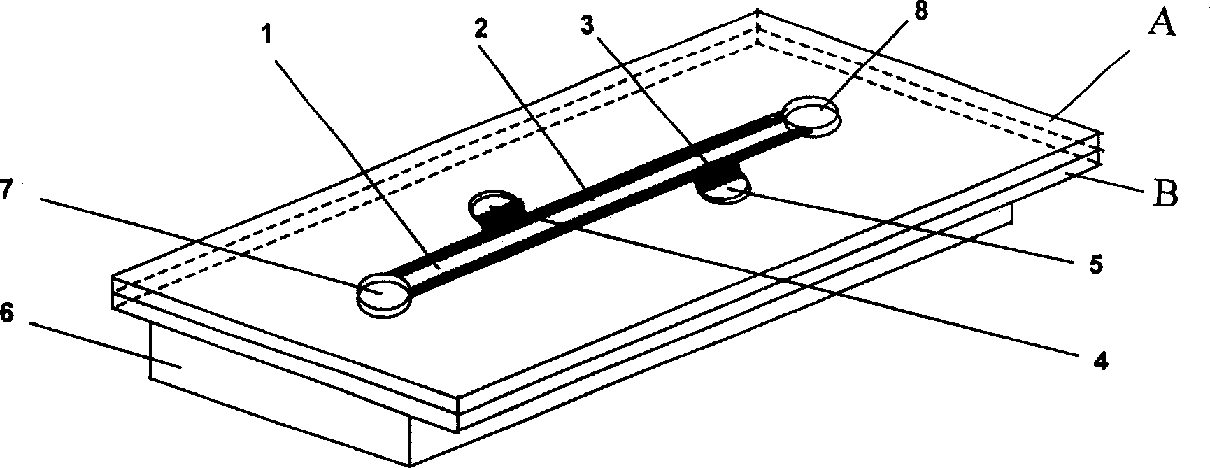
[0021] Such as figure 1 , figure 2 As shown, the present invention includes: a first base material A with two electrodes and two pipe inlets and outlets respectively, micro pipes are etched, and electrodes 2, 3 are sputtered on the two side walls of the whole micro pipes. The second base material B, the permanent magnet 6; the liquid storage tanks 7, 8 and the two electrode lead-out points 4, 5 at the two ends of the pipeline on the upper surface of the second base material B are respectively connected with the two electrodes on the first base material A The electrode and the inlet and outlet of the two pipes are aligned and bonded together, and a permanent magnet 6 is installed on the entire lower surface of the second base material B.

[0022] Such as figure 1 As shown, the micropipe whose cross-sectional shape is rectangular is a straight micropipe 1 .

[0023] Such as figure 2 , image 3 , Figure 4 Shown, said cross-sectional shape is that the micropipeline of rec...


PUM


Abstract

A magnetic fluid driven miniature pump is composed of the first substrate with two electric electrodes and the tube inlet and outlet, the second substrate with etched microtube, liquid torages and the electrodes formed on the two side walls of microtube by sputtering, and a permanent magnet installed onto lower surface of the second substrate. After two substrates are aligned and boand and the electrolyte is filled in said microtube, said electrodes are connected to positive and negative electrodes of power supply to generate current in the electrolyte. Under the action of said permanent magnet, a lorentz force is generated in the electrolyte to drive it to flow from one liquid storage to another.

Description

Technical field [0001] The invention relates to a micro flow control device, in particular to a magnetic fluid propelling micro pump. Background technique [0002] Magnetohydrodynamic micropump (MHDmicropump for short) is a new type of non-mechanical micropump, which uses Lorentz force to push the electrolyte solution to produce continuous flow, which can change the flow direction and produce controllable flow. Since the working medium is an electrolyte solution, which is compatible with chemical solutions, it can be used for the delivery and flow injection of biochemical drugs. At present, the micro electromagnetic pump has attracted the attention of more and more foreign MEMS scholars. South Korea's Jaesung Jang, Seung S.Lee designed a DC micro-electromagnetic pump, its Achilles' heel is that the voltage is slightly higher or the concentration of electrolyte ions in the solution is very easy to generate bubbles. Abraham P.Lee and his student Asuncion V.Lemoff designed th...

Claims


Application Information

Patent Timeline
Patent Type & Authority Applications(China)
IPC IPC(8): F04B17/04
Inventor 傅新刘玲谢海波杨华勇
Owner ZHEJIANG UNIV
Learn More