Eureka AIR delivers breakthrough ideas for toughest innovation challenges, trusted by R&D personnel around the world.

Lathe gang tool rest installation precision adjusting method

A technology of installation accuracy and adjustment method, which is applied in the field of lathe tool holders, can solve the problems of limited processing capacity, low processing accuracy, and heavy workload, and achieve the effects of eliminating position tolerance changes, improving machine adjustment efficiency, and improving surface hardness

Active Publication Date: 2021-03-30
SUZHOU SABO IND DESIGN
View PDF10 Cites 0 Cited by
  • Summary
  • Abstract
  • Description
  • Claims
  • Application Information

AI Technical Summary

Problems solved by technology

[0002] Due to its low cost, economical CNC lathes are still widely used by most enterprises and play an extremely important role in my country's manufacturing industry; The four-station automatic rotary tool post has a simple structure, flexible movement, and high repeat positioning accuracy. It has been used on economical CNC lathes, but its processing capacity is severely limited by the number of its own tool positions.
The four-station automatic rotary tool post can only be equipped with four knives under normal circumstances. The rough turning tool, finishing turning tool, threading knife, groove knife or cutting knife are used to process the external contour of the parts, but lack the processing of the internal contour. Capabilities, such as centering positioning holes, drilling, reaming, reaming and turning various internal contours, etc.
However, when such modification is used to make center positioning holes, drill holes, ream holes and ream holes, it is necessary to adjust the tool on the x-axis, y-axis and z-axis at the same time, which is extremely difficult to adjust, and each time a new part is processed or replaced midway All the knives need to be re-adjusted. The workload is heavy, the efficiency is low, and the technical requirements are high. A small adjustment error will directly damage the knives, and the machining accuracy is low, which cannot meet the modern high-efficiency and high-precision manufacturing requirements.

Method used


Image

  • Lathe gang tool rest installation precision adjusting method
  • Lathe gang tool rest installation precision adjusting method

Examples


Embodiment Construction

[0041] The technical solutions in the embodiments of the present invention will be clearly and completely described below in conjunction with specific embodiments of the present invention; obviously, the described embodiments are only part of the embodiments of the present invention, not all of them. Based on the embodiments of the present invention, all other embodiments obtained by persons of ordinary skill in the art without making creative efforts belong to the protection scope of the present invention.

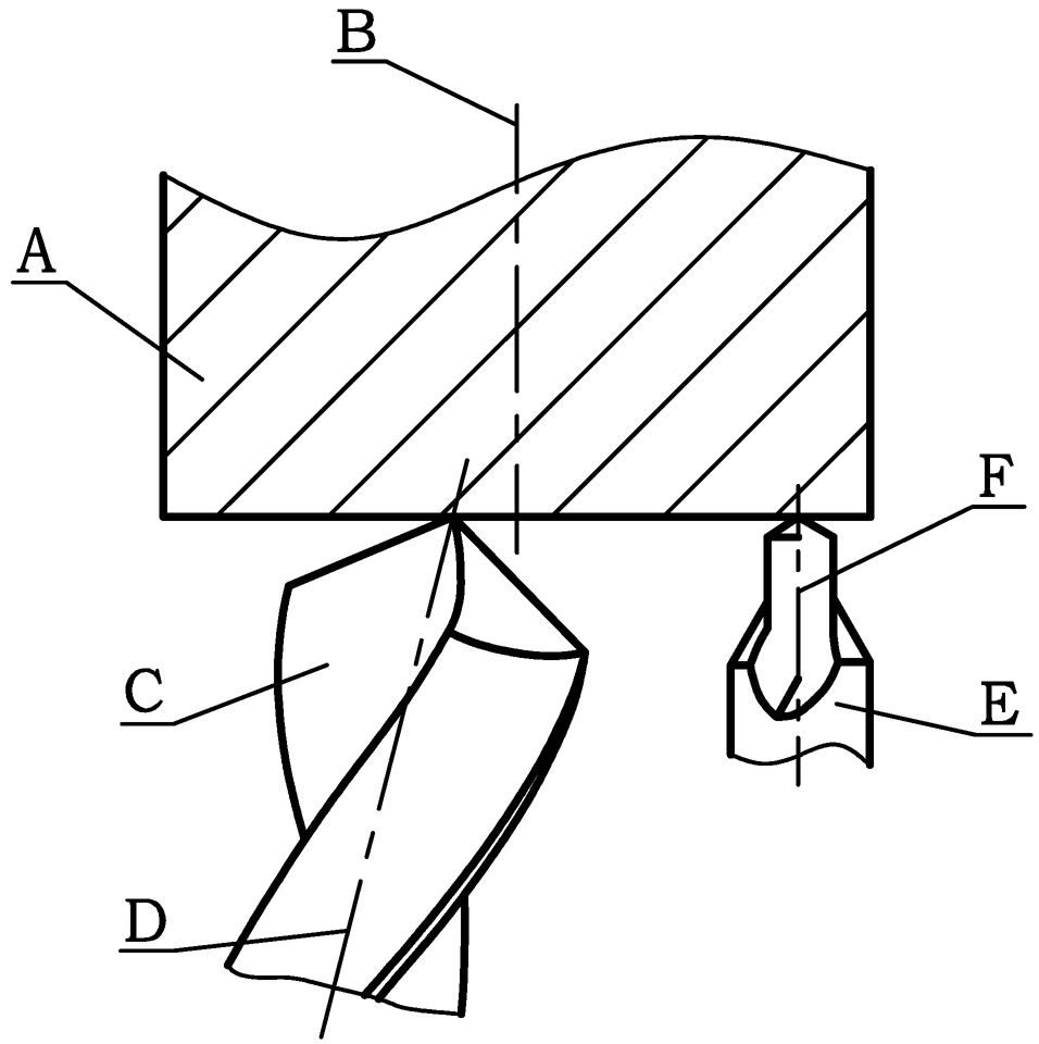
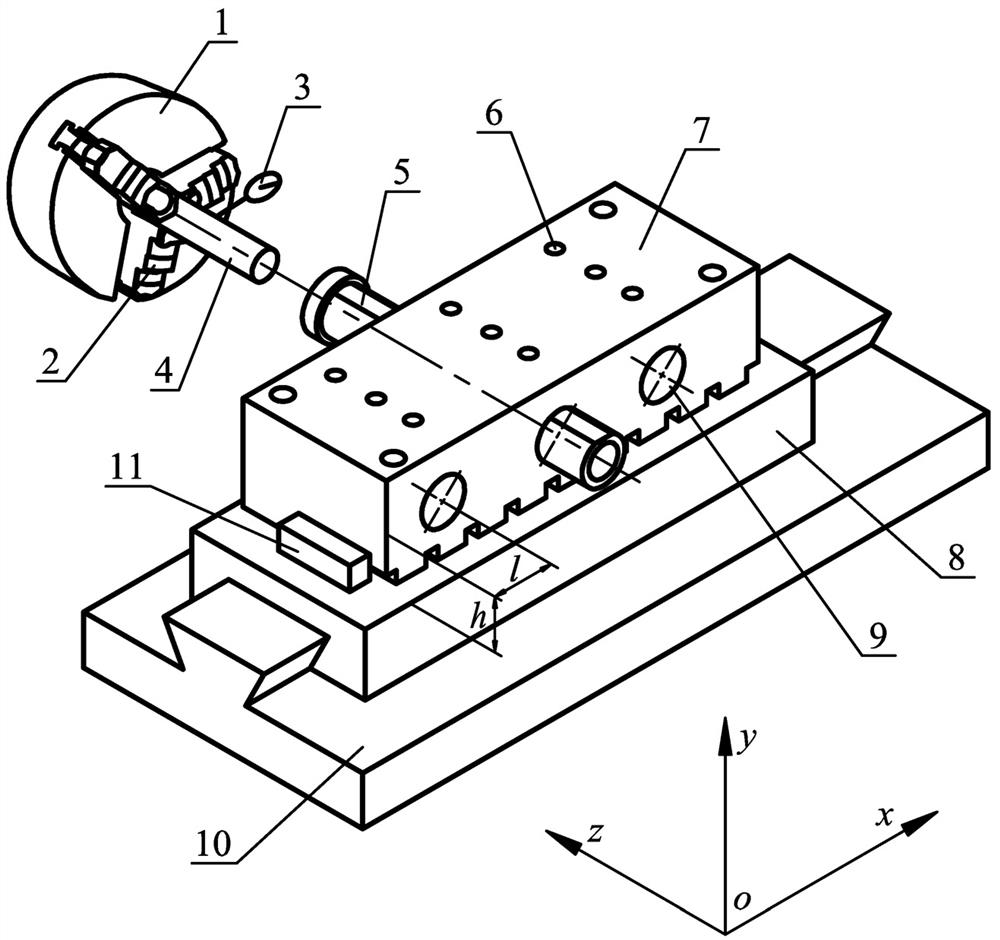
[0042] see figure 1 , figure 2 The tool position modification method of the economical CNC lathe, the main motion of the lathe processing is the rotary motion of the workpiece A, the tool only moves in translation but not rotates; the workpiece A is installed on the lathe chuck 1, and rotates with the main shaft, centering The installation and adjustment of drill E and twist drill C will produce deviations, and there will be a phenomenon that the centering drill center ...


PUM


Abstract

The invention provides a lathe gang tool rest installation precision adjusting method. According to the lathe gang tool rest installation precision adjusting method, a targeted gang tool rest structure is designed by analyzing the machining characteristics of lathe holes, and the gang tool rest installation precision adjusting method is formulated according to the structural characteristics and precision of a lathe; by additionally arranging the tool positions on a sliding plate, the machining capacity is improved, the designed gang tool rest installation precision adjusting method is suitablefor increasing the number of the lathe tool positions, the precision obtained through the gang tool rest installation precision adjusting method can meet the precision requirement of a machine tool,the machining precision of a refitted gang tool rest is improved to the maximum extent, rapid tool replacing is achieved, the toolsetting error is eliminated, the production efficiency is improved, the hole machining precision is improved to the maximum extent, and the high-precision and high-efficiency operation requirements of modern production and manufacturing are met.

Description

technical field [0001] The invention relates to the technical field of lathe tool holders, in particular to a method for adjusting the installation precision of a lathe tool holder. Background technique [0002] Due to its low cost, economical CNC lathes are still commonly used by most enterprises and play an extremely important role in my country's manufacturing industry; the four-station automatic rotary tool holder it has always used has simple structure, flexible movements, and repeatable It has high positioning accuracy and has been used on economical CNC lathes, but its processing capacity is severely limited by the number of tool positions. The four-station automatic rotary tool post can only be equipped with four knives under normal circumstances. The rough turning tool, finishing turning tool, threading knife, groove knife or cutting knife are used to process the external contour of the parts, but lack the processing of the internal contour. Capabilities, such as ce...

Claims


Application Information

Patent Timeline
IPC IPC(8): B23Q3/00B23B21/00B23B25/06B23B31/103
CPCB23Q1/25B23Q3/00B23B25/06B23B31/103
Inventor 张祝
Owner SUZHOU SABO IND DESIGN
Why Eureka
Eureka Blog
Learn More