Heating surface sectional arrangement device of biomass grate-fired boiler applied to high-temperature ultrahigh-pressure non-reheating system

A biomass layer and heating surface technology, applied in the direction of solid fuel combustion, combustion product treatment, combustion methods, etc., can solve the problems of increasing boiler cost, tail flue corrosion, and large flue gas resistance, etc., to achieve cost reduction, Avoid flue blockage, avoid wear and erosion effects

Pending Publication Date: 2021-03-26
上海动银科技有限公司
View PDF0 Cites 0 Cited by
  • Summary
  • Abstract
  • Description
  • Claims
  • Application Information

AI Technical Summary

Problems solved by technology

[0003] Although the application of this external water heat medium air preheater solves the corrosion of the tail flue caused by the condensation and precipitation of corrosive substances in the flue gas caused by directly heating the air with flue gas, it also brings the problem that it needs to be More heating surfaces are arranged at the tail of the boiler to heat the high-pressure feed water
[0004] like figure 1 As shown, the existing flue arrangement only "stuffs" all the heating surfaces into the last flue gas channel, resulting in a very compact arrangement of the heating surfaces in the last flue gas channel, resulting in a large resistance of the flue gas and a The air velocity is low, which is very easy to cause a large amount of dust accumulation in the flue
In addition, in order to arrange all the heating surfaces in the last flue gas channel, some boiler manufacturers will take measures to raise the boiler as a whole, which will greatly increase the cost of the boiler

Method used


Image

  • Heating surface sectional arrangement device of biomass grate-fired boiler applied to high-temperature ultrahigh-pressure non-reheating system
  • Heating surface sectional arrangement device of biomass grate-fired boiler applied to high-temperature ultrahigh-pressure non-reheating system

Examples


Embodiment Construction

[0025] In order to make the above objects, features and advantages of the present invention more comprehensible, the present invention will be further described in detail below in conjunction with the accompanying drawings and specific embodiments.

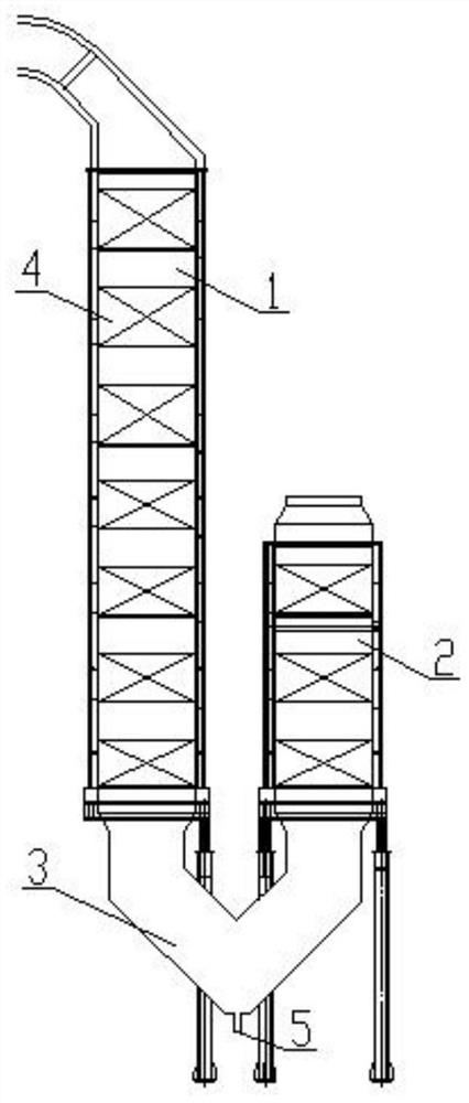
[0026] Such as figure 2 As shown, the present invention provides a segmented heating surface arrangement device for a biomass layer-fired boiler applied to a high-temperature, ultra-high pressure non-reheating system, which is characterized in that it includes a first flue gas channel 1, a second flue gas channel 2, Corner ash accumulation structure 3 and heating surface 4; wherein, the first flue gas passage 1 and the second flue gas passage 2 are arranged relatively left and right, and the first flue gas passage 1 and the second flue gas passage 2 They are connected to each other through the corner dust accumulation structure 3; the number of the heating surface 4 is multiple, which are respectively placed in the first flue gas...


PUM


Abstract

The invention provides a heating surface sectional arrangement device of a biomass grate-fired boiler applied to a high-temperature ultrahigh-pressure non-reheating system. The heating surface sectional arrangement device comprises a first flue gas channel, a second flue gas channel, a corner ash accumulation structure and heating surfaces, wherein the first flue gas channel and the second flue gas channel are oppositely arranged left and right, and the first flue gas channel and the second flue gas channel are connected and communicated with each other through the corner ash accumulation structure; and a plurality of heating surfaces are respectively arranged in the first flue gas channel and the second flue gas channel. According to the heating surface sectional arrangement device, sufficient heat exchange between flue gas and high-pressure feed water is facilitated, the boiler does not need to be raised to strive for a mounting space for the heating surfaces, and the overall heightof the boiler can be reduced through optimal design, so that the manufacturing cost of the boiler is greatly reduced, and the abrasion and erosion of ash to the heating surfaces are avoided; and the flue blockage caused by the accumulation of the ash in a tail flue is also avoided.

Description

technical field [0001] The invention relates to a segmented arrangement device for a heating surface of a biomass layer-fired boiler applied to a high-temperature, ultra-high-pressure non-reheating system. Background technique [0002] The principle of preheating the air of the biomass layer-fired boiler with an external water heat medium air preheater is to introduce high-pressure feed water at about 230 ° C into the tube of the external water heat medium air preheater, and the heating pipe flows outside The temperature of the air and high-pressure feed water decreases, so it needs to flow back to the heating surface arranged in the flue at the tail of the boiler to absorb heat again, and the temperature rises to 230°C. [0003] Although the application of this external water heat medium air preheater solves the corrosion of the tail flue caused by the condensation and precipitation of corrosive substances in the flue gas caused by directly heating the air with flue gas, it...

Claims


Application Information

Patent Timeline
Patent Type & Authority Applications(China)
IPC IPC(8): F23B30/08F23J3/00
CPCF23B30/08F23J3/00
Inventor 王凯
Owner 上海动银科技有限公司
Why Eureka
Try Eureka