
High-rotating-speed stirring friction adjusting method and welding tool with adjustable axial force of stirring needle

A technology of friction stir and adjustment method, which is applied in the direction of welding equipment, manufacturing tools, non-electric welding equipment, etc., and can solve problems such as unsuitable for high-speed stir-grinding welding, unsuitable for high-speed friction stir welding, and failure to reach high speed, etc. Achieve the effect of overcoming the problem of installation accuracy, good tolerance and simple structure

Active Publication Date: 2021-03-26
JIANGSU UNIV OF SCI & TECH
View PDF10 Cites 1 Cited by
  • Summary
  • Abstract
  • Description
  • Claims
  • Application Information

AI Technical Summary

Problems solved by technology

Therefore, the main problems of the current retraction device are: (1) The thin plate needs more precise gears to control the displacement, and the gears are easily damaged, which is not suitable for high-speed stirring, grinding and welding; (2) The retraction device has a large volume and a large moment of inertia , cannot reach high speed, and is not suitable for high-speed friction stir welding; (3) The coupling has a gap, which is acceptable for thick plate welding, but has low tolerance for thin plates, and is not suitable for high-speed friction stir welding

Method used


Image

  • High-rotating-speed stirring friction adjusting method and welding tool with adjustable axial force of stirring needle
  • High-rotating-speed stirring friction adjusting method and welding tool with adjustable axial force of stirring needle
  • High-rotating-speed stirring friction adjusting method and welding tool with adjustable axial force of stirring needle

Examples


Embodiment Construction

[0033] In order to better describe the technical solution of the present invention, the present application will be further described below in conjunction with the accompanying drawings.

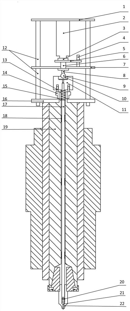
[0034] A high-speed friction stirring adjustment method with adjustable axial force of a stirring needle and a welding tool, including a stepping motor 2, the bottom of the stepping motor 2 is fixed on the top fixing device 1, and a pressure sensor is installed on the output shaft of the stepping motor 2 3. It is perpendicular to the horizontal plane and connects with the connecting plate 5. The first connecting rod 8 is fixed on the lower surface of the connecting plate 5. The other end of the first connecting rod 8 is fixed with a pressure ball 9. The linear bearing 6 is fixed on the middle fixing device. 7, the middle fixing device 7 is provided with a first threaded hole 73 for fixing with the linear bearing 5, and the first connecting rod 8 is matched with the linear bearing 5; the middl...


PUM


Abstract

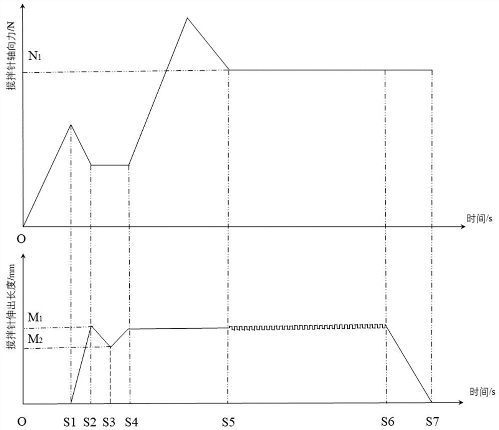
The invention discloses a high-rotating-speed stirring friction adjusting method and welding tool with adjustable axial force of a stirring needle, and belongs to the technical field of welding equipment. The high-rotating-speed stirring friction adjusting welding tool comprises a stepping motor, a connecting rod, a linear bearing, a connecting plate, a pressing ball, a ball bearing, a ball bearing connecting body, a T-shaped device, a fixing device, an electric main shaft, a bushing, a stirring needle connecting rod, a stirring needle and a shaft shoulder. Downward pressure is applied to thepressing ball through the stepping motor, upward elastic force is applied to the ball bearing connecting body through a spring, the devices are matched with each other, the pressing ball and the ballbearing are connected in a non-fastening mode, and axial displacement of the stirring needle is achieved. The real-time axial force of the stirring needle is obtained by subtracting the product of theelastic coefficient of the spring and the compression amount from the value measured by a pressure sensor mounted at the top end of a push rod of the stepping motor. The welding tool has the beneficial effects that the axial force of the stirring needle can be measured in real time, the compression type connection structure is simple, the tolerance is high, and a keyhole caused by high-rotating-speed friction stir welding can be eliminated.

Description

technical field [0001] The invention belongs to the technical field of welding equipment, and in particular relates to a high-speed stirring friction adjustment method with adjustable axial force of a stirring pin and a welding tool. Background technique [0002] Friction stir welding is a solid phase joining technique. The lifting of the stirring needle at the end of welding will leave a keyhole at the end of the weld, and it is very necessary to solve the keyhole problem in the engineering application process. At present, when friction stir welding is performed on thin plates, the welding method with a fixed stirring pin is mainly used, and the keyhole problem is still a major technical problem. The filling method of fusion welding, due to the high welding heat input, results in poor mechanical properties of the weld structure and large deformation of the thin plate; the filling friction stir welding method requires a large pressure to press the stopper into the rotation ...

Claims


Application Information

Patent Timeline
Patent Type & Authority Applications(China)
IPC IPC(8): B23K20/12B23K20/26
CPCB23K20/122B23K20/1245B23K20/1255
Inventor 陈书锦李志鹏孟令斐张皓张玉叶高阳陈鑫毅任剑剑牛文慧陈新元
Owner JIANGSU UNIV OF SCI & TECH
Learn More