Three-stage axial flow gas-liquid separation system with real-time control of T-shaped pipe network

A technology of real-time control and control system, applied in separation methods, liquid degassing, rapid degassing, etc., can solve the problems of low separation efficiency, long residence time, inability to separate small particle size droplets, etc. The effect of low volume and low gas content in the liquid

Active Publication Date: 2022-02-08
CHINA UNIV OF PETROLEUM (EAST CHINA)
View PDF8 Cites 0 Cited by
  • Summary
  • Abstract
  • Description
  • Claims
  • Application Information

AI Technical Summary

Problems solved by technology

Among them, the gravity separator has the advantages of simple structure, low processing and manufacturing cost, and can meet different gas-liquid separation conditions. However, its disadvantages are also obvious, that is, it needs to provide a large enough space, and rely on gravity for separation to make the residence time longer. The separation efficiency is low, and the critical droplet size that can be separated from natural gas cannot exceed 100 μm, so it is impossible to separate small-sized droplets in gas-liquid two-phase flow, which is only applicable to ground natural gas separation projects
The filter separator can effectively solve the problems of the gravity separator, such as large separation critical droplet size, low separation efficiency, and long separation residence time. However, the filter element, a key component of the filter separator, is prone to clogging during the separation process. As a result, the pressure drop of the gas-liquid two-phase fluid increases rapidly before and after separation, and the filter element of the separator needs to be replaced regularly, and when the filter element of the separator is reused, the cleaning and sewage discharge process is more complicated
The combined cyclone coalescer organically combines a multi-tube centrifugal separator and a wire mesh coalescer to solve the serious problem of secondary carryover when the gas-liquid two-phase flow is large. However, the combined separator is prone to Liquid flooding, the treatment effect on pollutants is poor, and it is easy to cause blockage, and the direction of liquid discharge will directly affect the separation efficiency, and the pressure drop of gas-liquid two-phase flow is large
Finally, it should be pointed out that the domestic research on compact and efficient gas-liquid separation technology is still in the experimental stage.

Method used


Image

  • Three-stage axial flow gas-liquid separation system with real-time control of T-shaped pipe network
  • Three-stage axial flow gas-liquid separation system with real-time control of T-shaped pipe network
  • Three-stage axial flow gas-liquid separation system with real-time control of T-shaped pipe network

Examples


Embodiment Construction

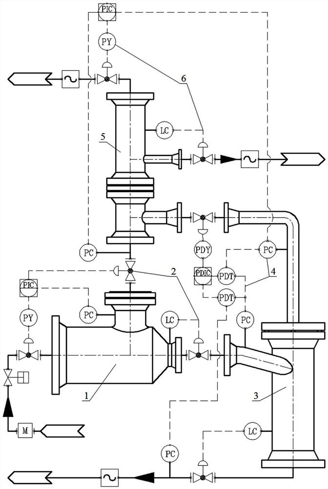
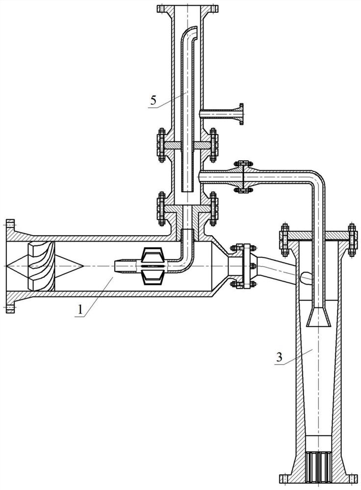
[0045] exist figure 1 and figure 2 Among them, the real-time-controlled T-shaped pipe network three-stage axial flow gas-liquid separation system includes the first-stage axial flow degasser 1, the first-stage axial flow degasser control system 2, the second-stage cyclone degasser 3, and the second-stage Cyclone degasser control system 4, third-stage jet degasser 5 and third-stage jet degasser control system 6, first-stage axial flow degasser 1, second-stage cyclone degasser 3 and third-stage jet The degassers 5 are connected by flanges to form a T-shaped pipe network and realize three-stage axial flow gas-liquid separation of gas-containing well fluid.

[0046] exist figure 1 and figure 2 Among them, the real-time-controlled T-shaped pipe network three-stage axial flow gas-liquid separation system is based on the first-stage axial flow degasser 1 to implement the first-stage four-stream axial flow rapid degassing operation, and removes most of the liquid phase of the gas...


PUM


Abstract

The invention provides a T-shaped pipe network three-stage axial flow gas-liquid separation device and a real-time control system, which are applied to deep and efficient degassing of gas-containing well liquid. The first-stage axial flow degasser adopts a horizontal columnar single-tube body and implements the first-stage four-strand axial flow rapid degassing operation to remove most of the liquid phase of the gas-containing well fluid to form a first-stage gas flow and a first-stage liquid flow. The first-stage cyclone degasser adopts a vertical column cone single-tube body and implements the second-stage single-strand cyclone rapid degassing operation to remove the remaining liquid phase of the first-stage liquid flow to form a second-stage gas flow and a second-stage liquid flow. The first-stage jet degasser adopts a vertical cylindrical double-pipe body and implements the third-stage reversing jet deep degassing operation to remove the small particle size droplets carried by the first-stage air flow and the second-stage air flow to form the third-stage air flow and the third-stage liquid. One-stage axial flow degassing control system, two-stage swirling flow degassing control system and three-stage jet degassing control system realize remote automatic control of degassing operations at all levels and automatic regulation of gas-containing well fluids as well as gas flows and liquids at all levels. Flow rate and flow pressure.

Description

technical field [0001] The invention relates to a high-efficiency gas-liquid separation method in the field of oil and gas field development and production engineering, in particular to a compact, T-shaped pipe network, three-stage axial flow degassing tubular gas-liquid separation device and its real-time control system and process process. Background technique [0002] The natural gas produced by oil and gas wells needs to be powered and then transported over long distances. The liquid phase components and impurities in natural gas will cause mechanical failures when fueling turbine power devices, and cause various degrees of pollution and damage to downstream equipment. , and the existence of liquid phase components will reduce the dew point of natural gas, and the lowering of temperature will cause the natural gas to precipitate liquid during the transportation process. Therefore, gas-liquid separation operations need to be carried out before natural gas gathering and tr...

Claims


Application Information

Patent Timeline
Patent Type & Authority Patents(China)
IPC IPC(8): B01D19/00
CPCB01D19/0036B01D19/0073B01D19/0042
Inventor 刘春花刘新福陈基郝忠献耿莉吴晓明郝爱刚刘峰王建峰王德祥
Owner CHINA UNIV OF PETROLEUM (EAST CHINA)
Why Eureka
Try Eureka