Dynamic seal adjustable shuttle wheel side brake reducer and shuttle car travel system

A reducer and adjustable technology, applied in the direction of brakes, brake components, transmission control, etc., can solve the problems of easy pollution, damage to the reducer, hidden dangers, etc., to improve operating safety and improve braking reliability. 、Accurate effect of angle limit

Active Publication Date: 2022-01-25
TAIYUAN INST OF CHINA COAL TECH & ENG GROUP +1
View PDF11 Cites 0 Cited by
  • Summary
  • Abstract
  • Description
  • Claims
  • Application Information

AI Technical Summary

Problems solved by technology

[0003] 1) The wheel reducer is directly connected to the tires to drive the shuttle car. The wheel brake is not installed. The brake is installed on the first-stage reducer, which is a high-speed brake. If any link of the reducer is damaged, it will directly affect the shuttle. Braking performance of the car, there is a serious safety hazard;
[0004] 2) The wheel reducer is responsible for the steering function of the shuttle car, and there is no steering mechanical limit device, which may easily cause interference between the tire steering and the drive shaft;
[0005] 3) There is no mechanical overload protection device, and the overload impact may easily cause serious damage to the reducer
[0009] 1) During the installation process, the connection between the ball cage coupling and the fixed component is not easy to adjust, and it is easy to cause excessive compression of the seal;
[0010] 2) The seal is exposed to the outside world for a long time and is easily polluted

Method used


Image

  • Dynamic seal adjustable shuttle wheel side brake reducer and shuttle car travel system
  • Dynamic seal adjustable shuttle wheel side brake reducer and shuttle car travel system
  • Dynamic seal adjustable shuttle wheel side brake reducer and shuttle car travel system

Examples


Embodiment 1

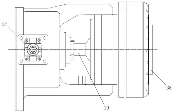
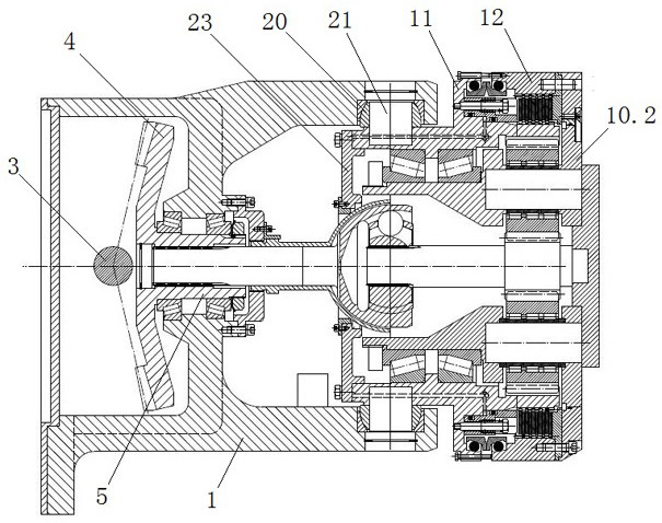
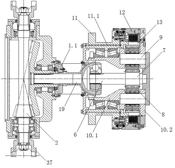
[0056] This embodiment provides a dynamic seal adjustable shuttle wheel rim brake reducer, including a hub 1, a first bevel gear 2, a first bevel gear shaft 3, a second bevel gear 4, a second bevel gear shaft 5, and a sun gear shaft 6. Sun gear 7, planetary gear 8, planetary gear shaft 9, planet carrier, first housing 11, second housing 12, inner ring gear 13, static friction plate 14, dynamic friction plate 15, piston 16, return screw 17 and return spring 18 ; The first bevel gear 2 is located in the hub 1, fixedly pierced with the first bevel gear shaft 3, the first bevel gear shaft 3 is connected to the hub 1 in rotation and both ends extend from the hub 1 to connect with the drive shaft; the second bevel gear The gear 4 is located in the hub 1 and meshes vertically with the first bevel gear 2. The second bevel gear shaft 5 is fixedly pierced. The second bevel gear shaft 5 is connected to the hub 1 in rotation and is connected to the sun gear shaft 6 through the cage couplin...

Embodiment 2

[0070] This embodiment provides a shuttle car traveling system. Two groups of traveling systems are longitudinally arranged on both sides of the shuttle car, including a motor 101, a first-stage reducer 102, a rear transmission shaft 103, a front transmission shaft 104, and rear wheel brakes for deceleration. 105 and the front wheel brake reducer 106, the motor 101 is connected with the primary reducer 102, the primary reducer 102 is connected with the rear wheel brake reducer 105 through the rear drive shaft 103, and the rear wheel brake reducer 105 is connected with the front wheel brake reducer 106 through the front transmission shaft 104, and the primary reducer 102 is provided with a parking brake 107; the rear wheel brake reducer 105 and the front wheel brake reducer 106 are all implemented The dynamic seal adjustable shuttle wheel brake reducer described in Example 1;

[0071] Both the parking brake 107 and the wheel brake reducer are controlled by a hydraulic system, a...


PUM


Abstract

The invention provides a dynamic seal adjustable shuttle wheel brake reducer and a shuttle car running system, which belong to the technical field of shuttle car accessories. The wheel brake reducer includes a hub, a first bevel gear, a first bevel gear shaft, Second bevel gear, second bevel gear shaft, sun gear shaft, sun gear, planetary gear, planetary gear shaft, planet carrier, first housing, second housing, ring gear, static friction plate, dynamic friction plate, piston, reset screw and reset The spring and the ball cage coupling are respectively connected with the first end cover and the hub cover installed on the wheel hub through the positioning assembly. The invention integrates the design of the brake and the wheel reducer, the final stage of braking, and other links other than the final stage are damaged, which does not affect the braking effect of the shuttle car and improves the braking reliability. The ball cage coupling is installed through the positioning component, The hexagonal nut and locking plate realize the controllable compression of the adjustable spherical seal, and the positioning protection snap ring has positioning and dustproof functions, which effectively prolongs the service life of the spherical seal.

Description

technical field [0001] The invention belongs to the technical field of shuttle car accessories, and specifically discloses a dynamic seal adjustable shuttle wheel side brake reducer and a shuttle car running system. Background technique [0002] The shuttle car is a trackless rubber-tyred vehicle for short-distance rapid transportation in coal mines. As one of the important equipment for short-wall mechanized mining, its main function is to transfer the coal from the continuous miner to the feeder crusher. At present, the deceleration system of the shuttle car mostly adopts a wheel-side decelerator of the shuttle car provided by the patent number ZL 201010290044.4. When the above deceleration system is actually used, there are the following deficiencies: [0003] 1) The wheel reducer is directly connected to the tires to drive the shuttle car. The wheel brake is not installed. The brake is installed on the first-stage reducer, which is a high-speed brake. If any link of the ...

Claims


Application Information

Patent Timeline
Patent Type & Authority Patents(China)
IPC IPC(8): B60K17/04B60T1/06F16H57/10F16H57/023F16H57/029F16H63/34
CPCB60K17/046B60T1/062F16H57/10F16H57/023F16H57/029F16H63/34
Inventor 马福文郭进彬马凯王炳效任晓力郭治富常映辉张学瑞吕继双申国建郭大武庞宇冀鹏飞
Owner TAIYUAN INST OF CHINA COAL TECH & ENG GROUP
Why Eureka
Try Eureka