
Travelling wave tube integrated power supply

A technology of integrated power supply and traveling wave tube, which is applied in the direction of electrical components, modification through conduction and heat transfer, and circuit arrangement on the support structure, etc. It can solve the problems of inability to meet the needs of miniaturized applications, high driving voltage, and inability to meet development needs, etc. question

Pending Publication Date: 2021-03-16
NO 12 RES INST OF CETC
View PDF0 Cites 0 Cited by
  • Summary
  • Abstract
  • Description
  • Claims
  • Application Information

AI Technical Summary

Problems solved by technology

However, the use of multiple independent power supplies makes the isolation design between power supplies complex and bulky, which cannot meet the miniaturization application requirements in the fields of vehicle transmitters and airborne decoy bombs.
[0004] Usually, in order to reduce the size of the traveling wave tube power supply, the method of sharing a converter is adopted. Due to the extremely high driving voltage required by the traveling wave tube, the lack of heat dissipation and high-voltage insulation technology limits the further miniaturization of the traveling wave tube power supply, resulting in The traveling wave tube power supply occupies about three-quarters of the volume of the microwave power module, which still cannot meet the development needs of modern electronic warfare electronic decoys and active phased arrays.

Method used


Image

  • Travelling wave tube integrated power supply
  • Travelling wave tube integrated power supply

Examples


Embodiment Construction

[0025] In order to illustrate the present invention more clearly, the present invention will be further described below in conjunction with preferred embodiments and accompanying drawings. Similar parts in the figures are denoted by the same reference numerals. Those skilled in the art should understand that the content specifically described below is illustrative rather than restrictive, and should not limit the protection scope of the present invention.

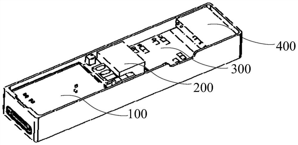
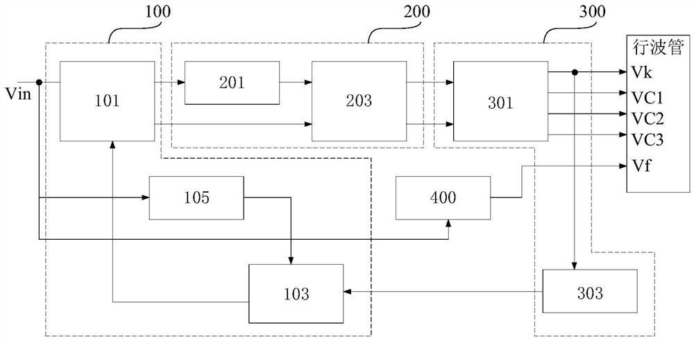
[0026] An embodiment of the present invention provides a traveling wave tube integrated power supply, which includes first to fourth circuit boards stacked in sequence, the first circuit board is provided with an inverter module, the second circuit board is provided with a boost module, and the second circuit board is provided with a booster module. A rectifier module is arranged on the third circuit board, and a filament module is arranged on the fourth circuit board, wherein

[0027] The inverter module is used to conver...


PUM


Abstract

The invention provides a travelling wave tube integrated power supply which comprises a first circuit board, a second circuit board, a third circuit board and a fourth circuit board which are sequentially arranged in a stacked mode. The first circuit board is provided with an inversion module. The second circuit board is provided with a boosting module. The third circuit board is provided with a rectification module. The fourth circuit board is provided with a filament module. The inversion module is used for converting an input first direct-current voltage signal into an alternating-current voltage signal; the boosting module is used for boosting the alternating-current voltage signal; the rectification module is used for converting the boosted alternating-current voltage signal into a second direct-current voltage signal and outputting the second direct-current voltage signal to a traveling-wave tube to be powered; and the filament module is used for supplying power to the filament of the travelling wave tube according to the first DC voltage signal. According to the invention, the power supply is set into a plurality of stacked modules according to circuit functions in the powersupply, miniaturization of the power supply is realized while heat dissipation is considered, and the power supply has a wide application prospect.

Description

technical field [0001] The invention relates to the technical field of power supplies, in particular to a traveling wave tube integrated power supply. Background technique [0002] Microwave power modules with high power density are widely used in modern electronic countermeasures, satellite communications and active phased arrays. Among them, the traveling wave tube is the core device of the microwave power module. The traveling wave tube needs multiple power supplies to cooperate with the power supply to work normally. This multiple power supply is collectively called the traveling wave tube power supply. The traveling wave tube power supply generally includes a filament power supply, a cathode power supply, an anode power supply, a grid power supply, and collector power supplies. [0003] Traditional TWT power supply design schemes include independent power supply parallel power supply scheme and series power supply scheme. Since independent power supply is used to suppl...

Claims


Application Information

Patent Timeline
IPC IPC(8): H02M1/00H05K7/02H05K7/20
CPCH02M1/00H05K7/023H05K7/2039
Inventor 高文雷刘银川陈银杏郭陈一王桠枫孙建辉王俊杰崔美娜
Owner NO 12 RES INST OF CETC
Learn More