
Dual-polarized filtering patch antenna with high selective gain

A high-selectivity, patch antenna technology, applied in the field of communication antennas, can solve the problems that the dual-polarization structure is not easy to realize, and achieve good frequency selection characteristics and economic applicability, light weight, and simple structure.

Active Publication Date: 2021-03-16
SOUTH CHINA UNIV OF TECH +1
View PDF22 Cites 3 Cited by
  • Summary
  • Abstract
  • Description
  • Claims
  • Application Information

AI Technical Summary

Problems solved by technology

[0006] Generally speaking, in the existing filter antenna design work, the main method is to cascade the antenna and the filter circuit, which requires an additional impedance transformation circuit or optimize the impedance characteristics between the resonator and the antenna to achieve matching; or Filtering performance is achieved by introducing a radiation null near the passband, but this makes dual-polarization structures difficult to implement

Method used


Image

  • Dual-polarized filtering patch antenna with high selective gain
  • Dual-polarized filtering patch antenna with high selective gain
  • Dual-polarized filtering patch antenna with high selective gain

Examples


Embodiment 1

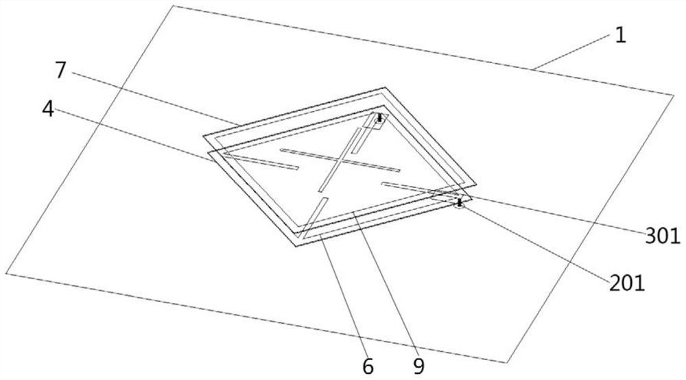
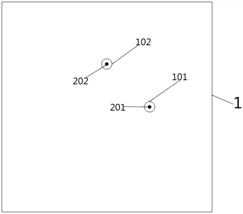
[0029] see Figure 1 to Figure 6 As shown, this embodiment provides a dual-polarized filter patch antenna with low frequency and high selective gain, which includes a metal reflective floor 1, a first dielectric substrate 4, a second dielectric substrate 7 and a first dielectric substrate arranged in sequence from bottom to top. Metal post 201, second metal post 202, first metal feed sheet 301 and second metal feed sheet 302;

[0030] A preset distance is maintained between the metal reflective floor 1 and the first dielectric substrate 4 to form a first air layer 10, the upper surface of the first dielectric substrate 4 is provided with a first copper clad layer 5, and the first The copper clad layer 5 is provided with a first rectangular patch 6, the first rectangular patch 6 is used as the main radiation source, and a preset distance is maintained between the first dielectric substrate 4 and the second dielectric substrate 7 to form a second air Layer 11, the upper surface...

Embodiment 2

[0036]The difference from Embodiment 1 is that this embodiment provides a dual-polarized filter patch antenna with high frequency and high selective gain, in which the heights of the first metal post 201 and the second metal post 202 are both 5 mm; the thickness of the first air layer 10 is 6 millimeters, and the thickness of the second air layer 11 is 8 millimeters; the first metal feed sheet 301 and the second metal feed sheet 302 are rectangular metal feed sheets, two metal feed sheets The length of the feed sheet is 17 mm, and the width is 8 mm; the length and width of the first rectangular patch 6 are 116 mm; the lengths of the four slot lines 601, 602, 603, 604 on the first rectangular patch 6 are 42 mm and a width of 3 mm; the length and width of the second rectangular patch 9 are 114 mm; the length of the cross-shaped groove line 901 on the second rectangular patch 9 is 57 mm and the width is 2 mm.

[0037] see Figure 10 Shown is the reflection coefficient S of the f...


PUM


Abstract

The invention discloses a dual-polarized filtering patch antenna with high selective gain. The dual-polarized filtering patch antenna comprises a metal reflection floor, a first dielectric substrate,a second dielectric substrate, a first metal column, a second metal column, a first metal feed sheet and a second metal feed sheet which are sequentially arranged from bottom to top, a preset distanceis kept between the metal reflection floor and the first dielectric substrate, a preset distance is kept between the first dielectric substrate and the second dielectric substrate, an air layer is formed, two input through holes are formed in the metal reflection floor, the metal feed pieces are connected with the input through holes through metal columns respectively, and the metal columns and the input through holes form input ports. The first dielectric substrate is provided with a first rectangular patch, the first rectangular patch is provided with four slot lines which extend from fourcorners of the first rectangular patch to the center and are not intersected with each other, the second dielectric substrate is provided with a second rectangular patch, and the center of the secondrectangular patch is provided with a cross-shaped slot line; the dual-polarized filtering patch antenna has impedance matching characteristics, and the rectangular patch is applied to introduce a radiation zero point, so that the dual-polarization structure is reserved, and the filtering performance is realized.

Description

technical field [0001] The invention relates to the technical field of communication antennas, in particular to a dual-polarization filter patch antenna with high selective gain. Background technique [0002] With the rapid development of modern communication systems, the performance requirements of various components inside the communication system are becoming more and more stringent. One of the solutions to meet the requirements of high-performance components is to use multifunctional devices, because it can reduce circuit size and improve system performance, such as filter antennas that achieve both filtering and radiation characteristics. In addition, dual polarization is an important performance index of base station antennas, so dual polarization filter antennas will definitely have a large demand. For the design of the filter antenna, many scholars have conducted a lot of research and exploration, and proposed many design methods, but some methods will affect the ga...

Claims


Application Information

Patent Timeline
Patent Type & Authority Applications(China)
IPC IPC(8): H01Q1/00H01Q9/04
CPCH01Q1/002H01Q9/0414H01Q9/045
Inventor 陈付昌梁根著向凯燃张海伟
Owner SOUTH CHINA UNIV OF TECH
Learn More