Agricultural automatic peanut shell breaking device
An automatic, shell technology, applied in the direction of shelling, application, pod removal, etc., can solve the problems of high labor intensity, peanut damage, low work efficiency, etc., to achieve the effect of collection effect
- Summary
- Abstract
- Description
- Claims
- Application Information
AI Technical Summary
Problems solved by technology
Method used
Image
Examples
Embodiment 1
[0076] An automatic shell breaking device for agricultural peanuts, such as figure 1 As shown, it includes a base 1, a first support column 2, a bracket 3, a pushing mechanism 4 and an extruding mechanism 5. The base 1 is provided with three first support columns 2, and the front side of the base 1 is provided with two brackets 3. A pushing mechanism 4 is arranged between the tops of the three first support columns 2 , and an extruding mechanism 5 is arranged on the left side of the upper front part of the base 1 .
[0077] When people want to shell peanuts, they can use this automatic shell breaking device for agricultural peanuts. First, the user collects the peanuts, then puts the peanuts into the push mechanism 4, and pushes the peanuts into the shell by starting the push mechanism 4. In the extruding mechanism 5, then push the extruding mechanism 5 downwards to break the shell of the peanuts to realize the effect of breaking the shell, then close the pushing mechanism 4, ...
Embodiment 2
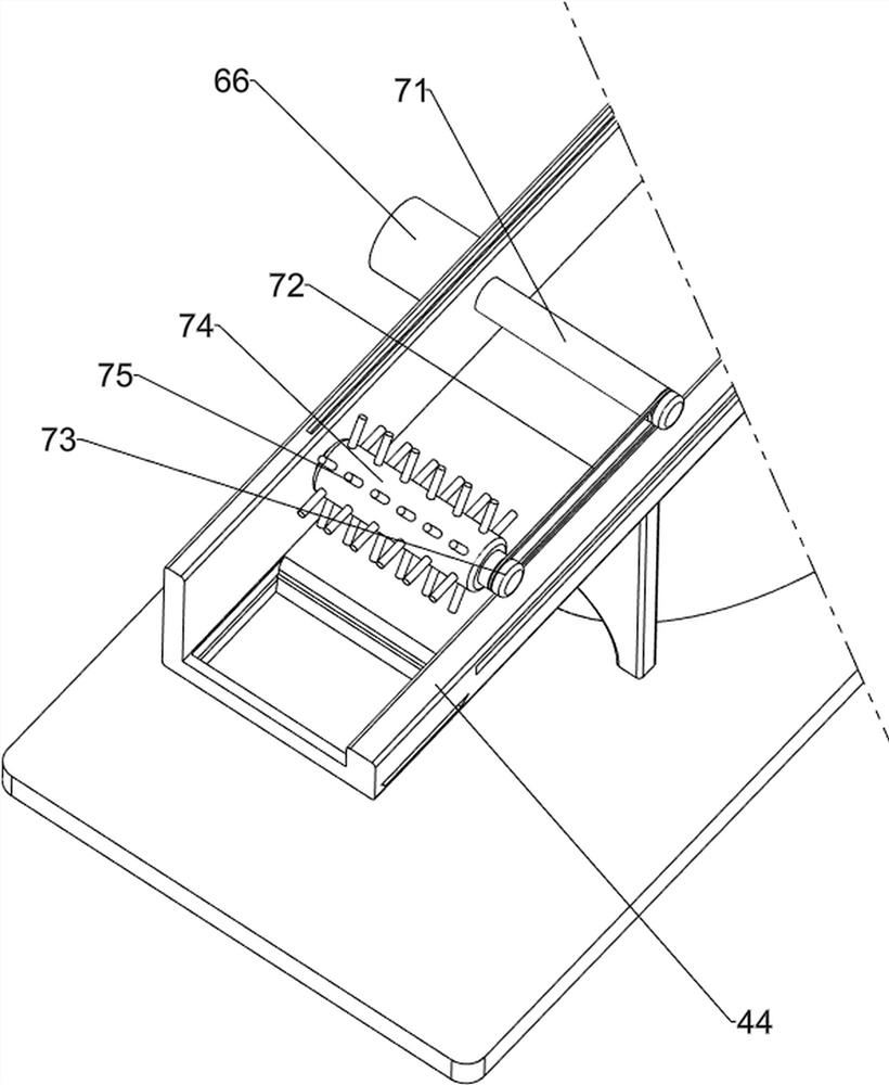
[0079] On the basis of Example 1, such as figure 2 and image 3 As shown, the pushing mechanism 4 includes a cylinder 41, a discharge plate 42, a first slide block 43, a stand 44 and a baffle plate 45, and a stand 44 is arranged between the tops of the three first support columns 2, and the stand 44 A cylinder 41 is installed on the top rear side, and the front end of the telescopic rod of the cylinder 41 is provided with a discharge plate 42, and the right part of the rear side of the discharge plate 42 is provided with a first slide block 43, and the first slide block 43 is slidably connected with the stand 44. The lower part of the front side of the frame 44 is slidably provided with a material blocking plate 45 .
[0080] The user places the peanuts on the discharge plate 42, activates the cylinder 41, and the telescopic rod of the cylinder 41 stretches forward, thereby driving the discharge plate 42 to move forward, and then drives the first slider 43 to move forward, a...
Embodiment 3
[0084] On the basis of Example 2, such as Figure 4-Figure 8 As shown, a reciprocating mechanism 6 is also included, and the left wall of the platform 44 is provided with a reciprocating mechanism 6, and the reciprocating mechanism 6 includes a second connecting rod 61, a third slider 62, a second rack 63, a third gear 64, a half Gear 65, the first rotating shaft 66, the second rotating shaft 67 and the first gear 68, the top of the first slider 43 is provided with the second connecting rod 61, and the left part of the rear side of the stand 44 is slidingly provided with the third sliding block 62 , the third slider 62 is connected with the second connecting rod 61, the left wall of the second connecting rod 61 is provided with a second rack 63, the left part of the front side of the stand 44 is rotatably provided with a first rotating shaft 66, and the first rotating shaft 66 right side is provided with the 3rd gear 64, and the 3rd gear 64 is meshed with the 2nd rack 63, and ...
PUM
 Abstract
Description
Claims
Application Information
 - R&D
- Intellectual Property
- Life Sciences
- Materials
- Tech Scout
- Unparalleled Data Quality
- Higher Quality Content
- 60% Fewer Hallucinations
Browse by: Latest US Patents, China's latest patents, Technical Efficacy Thesaurus, Application Domain, Technology Topic, Popular Technical Reports.
© 2025 PatSnap. All rights reserved.Legal|Privacy policy|Modern Slavery Act Transparency Statement|Sitemap|About US| Contact US: help@patsnap.com


