
Pre-oxidation furnace for carbon fiber production

A pre-oxidation furnace and carbon fiber technology, applied in the fields of fiber chemical characteristics, textiles and papermaking, etc., can solve the problems of increased hot air resistance of tow knots, inconsistent speed of tow travel, and increased production hazards, etc.

Pending Publication Date: 2021-03-12
舒刚勇
View PDF0 Cites 0 Cited by
  • Summary
  • Abstract
  • Description
  • Claims
  • Application Information

AI Technical Summary

Problems solved by technology

[0003] When the hot air blows through the tow from top to bottom, there is a certain temperature gradient in the vertical direction, and the temperature at the top is greater than the temperature at the bottom, which leads to the pre-oxidation rate of the tow at the top being greater than that at the bottom. The effect of pre-oxidation is the same, but the speed of the tow at the two places is inconsistent, which increases the difficulty and precision of production control. At the same time, the top tow is subjected to continuous high temperature, which is easy to form heat accumulation, which will cause fire and burnout, increasing the danger of production.
[0004] The hot air blows vertically downwards, and the tow moves horizontally, so the two are in a vertical state. When producing a large tow of carbon fiber, because the tow is wider, the gap between the tow and the tow is relatively smaller, which is easy to cause The resistance of the tow knot hot air is increased, and it is difficult for the hot air to pass through the tow. The small molecules and reaction heat generated by the pre-oxidation reaction are not easy to be taken away in time, which affects the quality of the carbon fiber. At the same time, the resistance of the tow to the hot air is large , the flow of hot air may cause the bundle to vibrate and cause the bundle to break

Method used


Image

  • Pre-oxidation furnace for carbon fiber production
  • Pre-oxidation furnace for carbon fiber production
  • Pre-oxidation furnace for carbon fiber production

Examples


Embodiment Construction

[0018] The following will clearly and completely describe the technical solutions in the embodiments of the present invention with reference to the accompanying drawings in the embodiments of the present invention. Obviously, the described embodiments are only some, not all, embodiments of the present invention. Based on the embodiments of the present invention, all other embodiments obtained by persons of ordinary skill in the art without making creative efforts belong to the protection scope of the present invention.

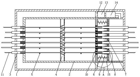
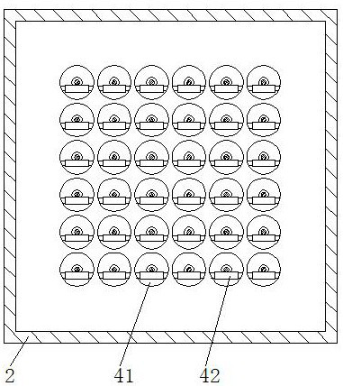
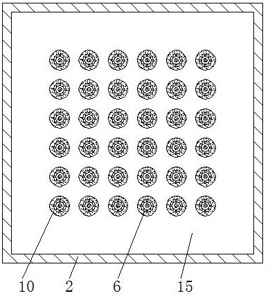
[0019] see Figure 1-4 , a pre-oxidation furnace for carbon fiber production, comprising an overcoat 1, a tow 11, a blower 13 and a heater 14, the top of the inner cavity of the overcoat 1 is provided with an air intake hole 12, and the air intake hole 12 communicates with the blower 13 through a conduit, and the blower 13 communicates with the heater 14 through the conduit, and the lining tube 3 is fixedly installed on the left side wall of the jacket 1, and ...


PUM


Abstract

The invention relates to the technical field of carbon fiber production, and discloses a pre-oxidation furnace for carbon fiber production. The pre-oxidation furnace comprises an outer sleeve, tows, an air blower and a heater, wherein an air collecting hole is formed in the top of an inner cavity of the outer sleeve; the air collecting hole communicates with the air blower through a guide pipe; and the air blower communicates with the heater through a guide pipe. Through the arrangement of a supporting pipe and a movable plate, when hot air is injected into the right side of the movable plate,the movable plate is pushed to move leftwards after the pressure becomes larger and larger and reaches a certain pressure value, a conical nozzle is movably connected with a high-temperature-resistant rubber sleeve II in a sleeved mode, a ventilation groove channel in the supporting pipe is opened, the hot air on the right side of the movable plate is ejected leftwards in parallel with relativelyconstant pressure along a ventilation groove to heat the tows, the hot air and the tows are in a horizontal state, a certain temperature gradient is presented in an oxidation furnace from right to left, and the temperature is sequentially decreased from right to left, so that the tows are gradually heated and pre-oxidized after entering the oxidation furnace from the left side of the oxidation furnace.

Description

technical field [0001] The invention relates to the technical field of carbon fiber production, in particular to a pre-oxidation furnace for carbon fiber production. Background technique [0002] Carbon fiber is a high-tech fiber material developed rapidly in the 1960s. Due to its high specific strength, high specific modulus, and excellent heat resistance, chemical corrosion resistance, friction resistance and other properties, in the production process of carbon fiber, the pre-oxidation of the precursor plays a role of linking the past and the future, and the pre-oxidation process of the precursor directly Affecting the yield and performance of carbon fiber, the pre-oxidation furnace is currently used to pre-oxidize the raw silk. Tow, so that the tow has a pre-oxidation reaction, and after being filtered and reheated from the circulating air outlet of the lower layer, it is circulated again from the top, but there are some deficiencies in the use process, as follows: [...

Claims


Application Information

Patent Timeline
IPC IPC(8): D01F9/12
CPCD01F9/12
Inventor 舒刚勇
Owner 舒刚勇
Learn More