
Multi-directional welding device for circuit board

A welding device and multi-directional technology, applied in the direction of assembling printed circuits with electric components, auxiliary devices, welding equipment, etc., can solve the problems that circuit boards cannot be welded in multiple directions, achieve welding effects, facilitate welding, and improve welding efficiency Effect

Inactive Publication Date: 2021-03-12
合肥迅驰电子科技有限责任公司
View PDF12 Cites 0 Cited by
  • Summary
  • Abstract
  • Description
  • Claims
  • Application Information

AI Technical Summary

Problems solved by technology

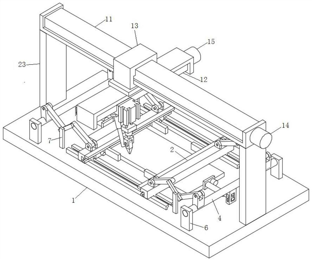
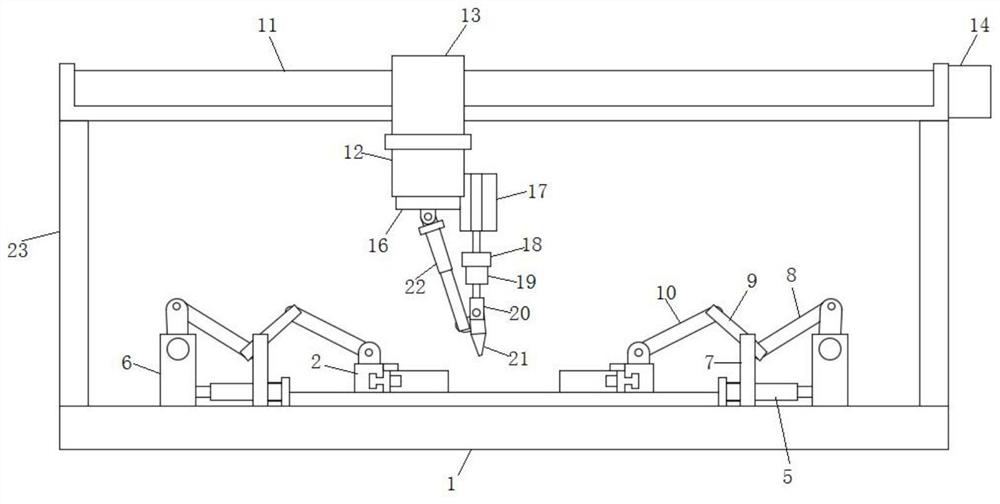
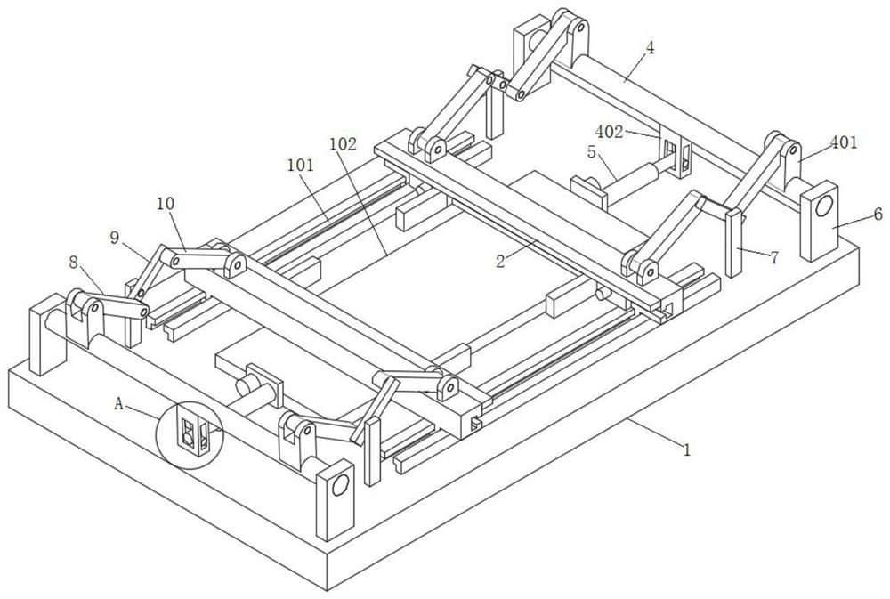
[0003] The object of the present invention is to provide a multi-directional welding device for circuit boards. The circuit board is fixed by a fixing fixture assembly, and the drive assembly is used to control the movement of the welding assembly in the X direction and the Y direction, which solves the problem of the existing circuit board. The technical problem that the board cannot be welded in multiple directions

Method used


Image

  • Multi-directional welding device for circuit board
  • Multi-directional welding device for circuit board
  • Multi-directional welding device for circuit board

Examples


Embodiment Construction

[0027] The following will clearly and completely describe the technical solutions in the embodiments of the present invention with reference to the accompanying drawings in the embodiments of the present invention. Obviously, the described embodiments are only some, not all, embodiments of the present invention. Based on the embodiments of the present invention, all other embodiments obtained by persons of ordinary skill in the art without creative efforts fall within the protection scope of the present invention.

[0028] In the description of the present invention, it should be understood that the terms "sliding hole", "upper", "lower", "inner wall", "bottom", "middle", "length", "inner", "both sides" Indicating orientations or positional relationships, etc., are only for the convenience of describing the present invention and simplifying the description, but do not indicate or imply that the components or elements referred to must have a specific orientation, be constructed ...


PUM


Abstract

The invention discloses a multi-directional welding device for a circuit board, and relates to the technical field of circuit board processing. The multi-directional welding device comprises a fixingclamp assembly, a driving assembly and a welding assembly. The fixing clamp assembly comprises a base. A pair of positioning plates are symmetrically connected to the base in a sliding mode, a work table is fixedly connected to the base, the driving assembly comprises an X-axis transmission device, an X-axis driving motor, a Y-axis transmission device and a Y-axis driving motor, the X-axis transmission device is fixedly connected to the upper portion of the base through a pair of vertical beams, and a first sliding base is connected to the X-axis transmission device in a sliding mode. The Y-axis transmission device is fixedly connected to the bottom of the first sliding base, a second sliding base is connected to the Y-axis transmission device in a sliding mode, and the welding assembly isfixedly connected to the second sliding base. The welding assembly can be controlled to move in the X direction and the Y direction through the driving assembly, the inclination degree of a welding gun can be adjusted through electric push rods, the motors can control the welding gun to rotate by 360 degrees, and therefore the all-directional welding effect is achieved.

Description

technical field [0001] The invention belongs to the technical field of circuit board processing, in particular to a multi-directional welding device for circuit boards. Background technique [0002] With the development of electronic information technology, circuit boards are widely used in people's production and life. The circuit board is obtained by soldering electronic components on the main board of the circuit board. When processing the circuit board, it is necessary to first insert the electronic components into the reserved electronic component mounting holes on the circuit board, and then solder each electronic component on one side of the circuit board. However, when soldering circuit boards, due to the various types of electronic components to be soldered, the displacement of electronic components is very likely to occur, thereby affecting the welding effect. Some electronic components are limited by their shapes and specifications, and the fixing operation is tr...

Claims


Application Information

Patent Timeline
Patent Type & Authority Applications(China)
IPC IPC(8): B23K37/00B23K37/02B23K37/04H05K3/34B23K101/36
CPCB23K37/00B23K37/0443B23K37/0247B23K37/0252H05K3/34B23K2101/36
Inventor 胡建军
Owner 合肥迅驰电子科技有限责任公司
Learn More