Coating sand mill for producing environment-friendly low-carbon coating

A sand mill and paint technology, which is applied in cleaning methods and utensils, smoke removal, grain treatment, etc., can solve the problems of paint can not achieve good conveying effect, unfavorable paint discharge and conveying, and poor cylinder cooling effect, etc. Achieve the effect of improving the grinding effect, reducing the failure rate and ensuring the cooling effect

Active Publication Date: 2021-03-12
CHONGQING XINGYU POLYMER PAINT +1
View PDF8 Cites 2 Cited by
  • Summary
  • Abstract
  • Description
  • Claims
  • Application Information

AI Technical Summary

Problems solved by technology

[0003] When the above-mentioned paint sanding machine is in use, the temperature is cooled by water cooling. Since the drive of the water cooling system operates independently, the inflow and outflow of water flow is carried out at a constant speed. When the water flow speed is controlled too high, although it can achieve better cooling effect, but it will cause a great waste of water resources, and the water heat absorption efficiency is not high; when the speed of the controlled water flow is too small, the cooling effect on the cylinder is not good, and it is difficult to achieve the purpose of cooling; at the same time, due to the sand mill During the stacking process, the material storage device is prone to compaction, which is not conducive to the discharge and transportation of paint. In addition, in the process of discharging materials from the storage device, it is often necessary to rely on external forces for suction. To complete the unloading, it not only needs to consume additional power, but also cannot achieve a good conveying effect for the paint inside the storage device

Method used


Image

  • Coating sand mill for producing environment-friendly low-carbon coating
  • Coating sand mill for producing environment-friendly low-carbon coating
  • Coating sand mill for producing environment-friendly low-carbon coating

Examples


Embodiment

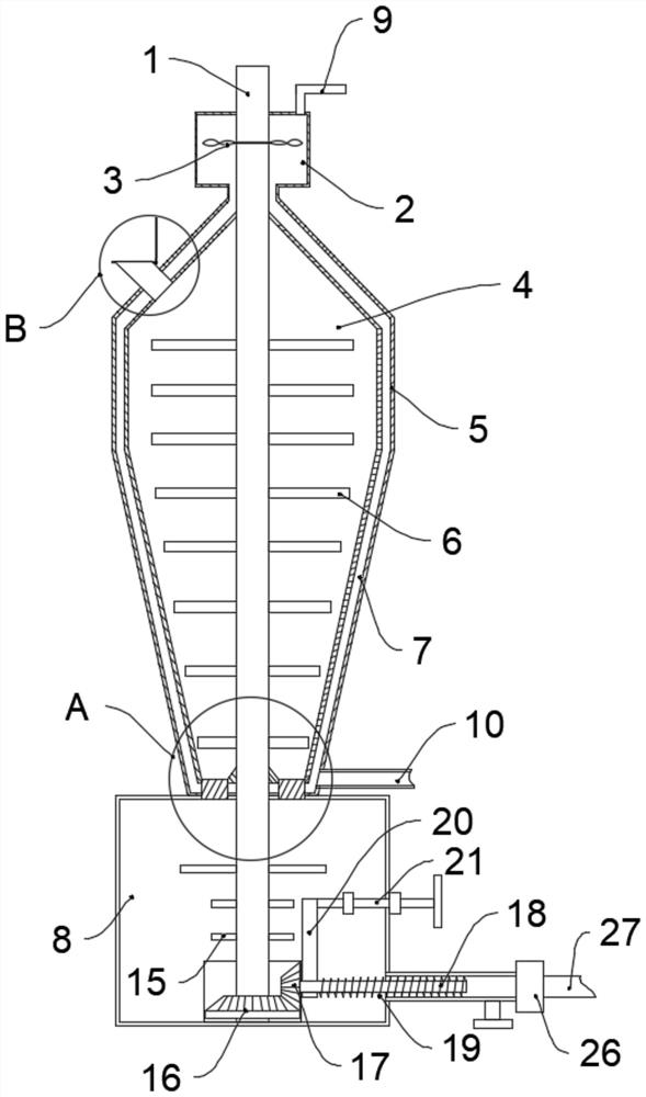
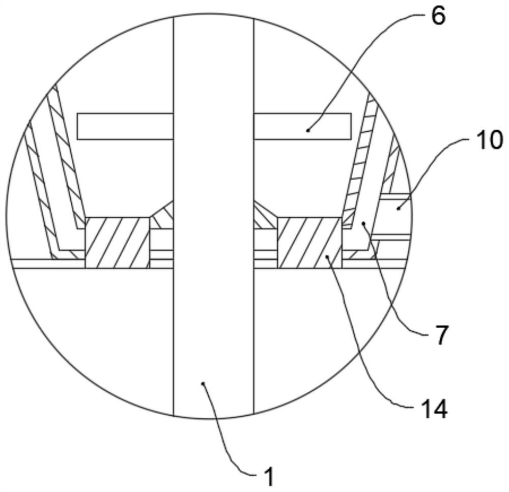
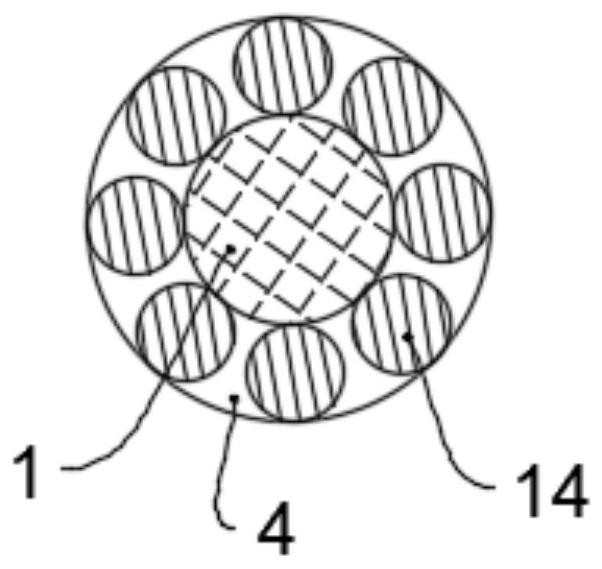
[0029] like Figure 1-5 As shown, a paint sand mill for producing environmentally friendly low-carbon paints includes a motor output end 1 fixedly connected to the motor, a cold water chamber 2 is provided at the lower part of the motor output end 1, and a drainage impeller 3 is arranged inside the cold water chamber 2 , the drainage impeller 3 is fixedly sleeved on the motor output end 1, and the drainage impeller 3 can be driven to rotate while the motor output end 1 is rotating. Sanding balls, the side of the motor output end 1 is fixedly connected with a plurality of grinding sheets 6, and the grinding sheets 6 rotate with the rotation of the motor output end 1, and the outer side of the sanding cylinder 4 is provided with a cooling outer partition 5, and the cooling outer A water cooling layer 7 is arranged between the partition plate 5 and the sand grinding cylinder 4, the upper end of the water cooling layer 7 communicates with the lower side of the cold water chamber 2...


PUM


Abstract

The invention belongs to the technical field of coating production equipment, and particularly relates to a coating sand mill for producing an environment-friendly low-carbon coating. The coating sandmill comprises a motor output end fixedly connected with a motor, a cold water chamber is arranged on the lower portion of the motor output end, a drainage impeller is arranged in the cold water chamber, the drainage impeller is fixedly arranged at the motor output end in a sleeving mode, a sand milling cylinder is arranged below the cold water chamber, a plurality of grinding pieces are fixedlyconnected to the side face of the motor output end, the outer side of the sand milling cylinder is sleeved with a cooling outer partition plate, a water passing cooling layer is arranged between the cooling outer partition plate and the sand milling cylinder, the upper end of the water passing cooling layer communicates with the lower side of the cold water chamber, a plurality of sieve holes which are annularly distributed by taking the motor output end as the circle center are formed in the bottom of the sand milling cylinder, a screen is arranged in each sieve hole, and a storage chamber isarranged at the lower end of the sand milling cylinder. According to the coating sand mill, cooling water can be greatly saved, and meanwhile, the cooling effect of the sand milling cylinder is guaranteed.

Description

technical field [0001] The invention belongs to the technical field of paint production equipment, in particular to a paint sand mill for producing environmentally friendly low-carbon paint. Background technique [0002] The paint sand mill is a processing equipment for stirring and grinding the paint during the paint production process. The currently used paint sand mill includes a grinding cylinder with a feed inlet and a discharge outlet, a cooling jacket is provided outside the grinding cylinder, and a water inlet and a water outlet are provided on the cooling jacket. The body is provided with grinding beads, a rotating shaft, and a screen. One end of the rotating shaft passes through the grinding cylinder and is connected to the motor through a mechanical transmission mechanism. Several grinding discs are welded on the rotating shaft located in the grinding cylinder. When working, the paint is input into the grinding cylinder from the feed port, and the motor drives th...

Claims


Application Information

Patent Timeline
IPC IPC(8): B02C17/10B02C17/16B02C17/18B02C23/02B02C17/24B08B15/02
CPCB02C17/10B02C17/163B02C17/18B02C17/1815B02C17/183B02C17/24B08B15/02
Inventor 王瀚平谢方奎
Owner CHONGQING XINGYU POLYMER PAINT
Why Eureka
Try Eureka