Flexible supporting structure of metal reflector

A technology of metal mirrors and flexible supports, applied in mirrors, installation, optics, etc., can solve problems such as poor assembly process, non-use of equipment research and development, difficult disassembly of mirrors and backplanes, etc., to improve manufacturing efficiency and reliability The effects of stability, ease of rapid mass manufacturing, and simplified design complexity

Pending Publication Date: 2021-03-09
CHANGCHUN INST OF OPTICS FINE MECHANICS & PHYSICS CHINESE ACAD OF SCI
View PDF10 Cites 1 Cited by
  • Summary
  • Abstract
  • Description
  • Claims
  • Application Information

AI Technical Summary

Problems solved by technology

[0007] 1. Poor temperature stability
[0008] The reflector and backplate are made of different materials, which cannot achieve thermal stability over a large temperature range;
[0009] 2. Poor installation reliability
[0010] The mirror and the backplane are connected by glue, and the glue layer may fail under extreme environmental conditions, which may cause the mirror and the backplane to separate;
[0011] 3. Poor assembly process
[0012] When the assembly and bonding of the reflector and the backplane have a large stress, it is difficult to disassemble the reflector and the backplane, and the processability of assembly is poor;
[0013] 4. Low processing efficiency
[0014] The reflector is processed in the form of traditional grinding and polishing, and the reflector and the back plate need to be processed separately and then combined, which cannot achieve rapid and low-cost mass production without using equipment for research and development;
[0015] 5. Poor consistency between assembly datum and optical datum
[0017] 6. Poor stress unloading ability
[0018] The flexible design of the support structure only considers the flexible unloading in terms of installation flatness, and ignores the introduction of stress around the screw rotation direction when the screw is pre-tightened, so that the mirror cannot withstand a large screw pre-tightening force, and the screw pre-tightening force needs to be increased to resist extreme Poor stress unloading ability under mechanical and thermal conditions

Method used


Image

  • Flexible supporting structure of metal reflector
  • Flexible supporting structure of metal reflector
  • Flexible supporting structure of metal reflector

Examples


Embodiment Construction

[0049] In order to make the object, technical solution and advantages of the present invention clearer, the present invention will be further described in detail below in conjunction with the accompanying drawings and specific embodiments. It should be understood that the specific embodiments described here are only used to explain the present invention, but not to limit the present invention.

[0050] The integrated design and flexible supporting structure of the metal reflector provided by the present invention will be described in detail below through specific embodiments.

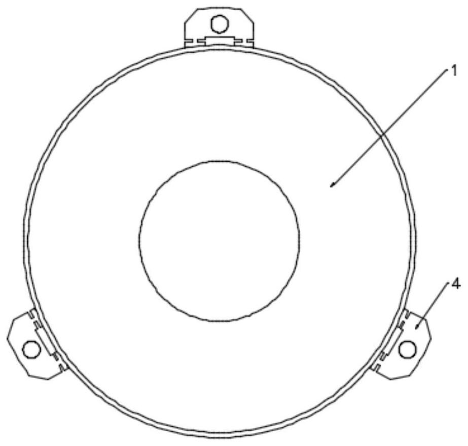
[0051] Such as figure 2 with Figure 4 It shows the structure of an integrated design and flexible support structure of a metal reflector of the present invention, including a circular reflector 1 with a fan-shaped lightweight structure 3 processed on the back, and a support back plate 2 integrally processed with the reflector 1 , flexible support ears 4 processed on the support backplane 2 and stres...


PUM


Abstract

The invention provides a metal reflector integrated design and low-stress installation flexible supporting structure suitable for a powerful environment. The structure comprises a reflector, a supporting back plate and a fan-shaped lightweight structure; the reflector and the supporting back plate adopt an integrated structure design, and a flexible supporting lug, a stress isolation groove and aweight reduction rectangular groove are processed on the supporting back plate. By means of the fact that the metal reflector has good machinability, the reflector base body and the supporting back plate can be subjected to integrated structural design, a flexible structure is directly machined on the back of the metal reflector, force and heat unloading of the installation environment is achieved, and therefore stress-free installation of the reflector is achieved.

Description

technical field [0001] The invention relates to the field of reflector design and its support structure, in particular to an integrated design of a metal reflector suitable for a strong mechanical environment and a flexible support structure for low-stress installation. Background technique [0002] As the load of aerospace optical systems gradually develops in the direction of light weight, high rigidity, high stability, and high cost performance, the design of optical mirrors needs to be more lightweight and integrated. Generally, when glass materials or ceramic materials are used to manufacture reflectors, metal materials with similar linear expansion coefficients are often used as the support back plate of the reflector, because the linear expansion coefficients of the materials used for the reflector and the back cannot match in a large temperature range , so the environmental adaptability of the optical system is poor, and it cannot achieve better imaging quality in a ...

Claims


Application Information

Patent Timeline
Patent Type & Authority Applications(China)
IPC IPC(8): G02B7/182G02B5/08
CPCG02B5/08G02B7/182
Inventor 谭双龙张新史广维王灵杰付强刘洋吴洪波胡铭钰闫磊赵尚男刘铭鑫
Owner CHANGCHUN INST OF OPTICS FINE MECHANICS & PHYSICS CHINESE ACAD OF SCI
Why Eureka
Try Eureka