Test equipment and test method for evaluating uniform corrosion of metal materials

A test equipment, a technology of uniform corrosion, applied in the direction of analysis of materials, weather resistance/light resistance/corrosion resistance, instruments, etc., can solve the problem of inaccurate test results, and achieve the effect of improving accuracy and scientificity, and reasonable structure design.

Pending Publication Date: 2021-03-09
SUZHOU NUCLEAR POWER RES INST +2
View PDF10 Cites 0 Cited by
  • Summary
  • Abstract
  • Description
  • Claims
  • Application Information

AI Technical Summary

Problems solved by technology

[0004] In view of this, in order to overcome the defects of the prior art and achieve the above object, the object of the present invention is to provide an improved test equipment for evaluating the uniform corrosion of metal materials, which can avoid the inaccurate test results caused by the contact between the material and the equipment in the traditional test. exact question

Method used


Image

  • Test equipment and test method for evaluating uniform corrosion of metal materials
  • Test equipment and test method for evaluating uniform corrosion of metal materials
  • Test equipment and test method for evaluating uniform corrosion of metal materials

Examples


Embodiment 1

[0030] Example 1 Test equipment for evaluating uniform corrosion of metallic materials

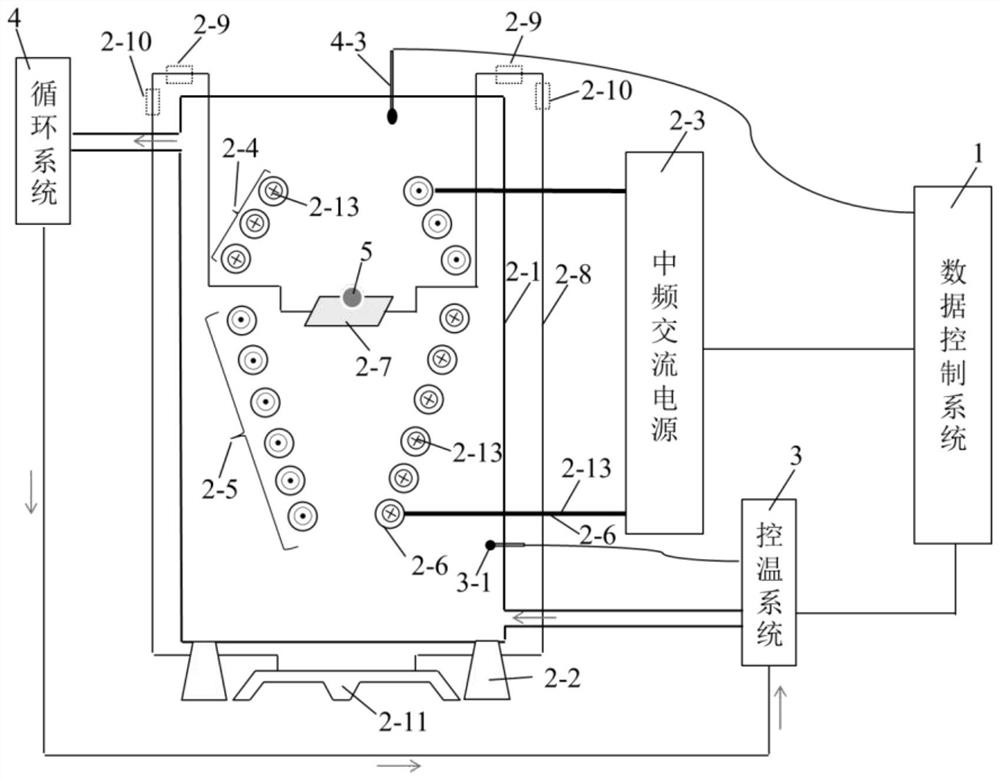
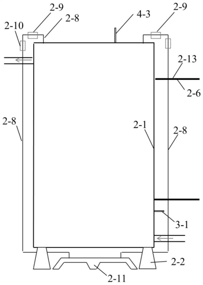
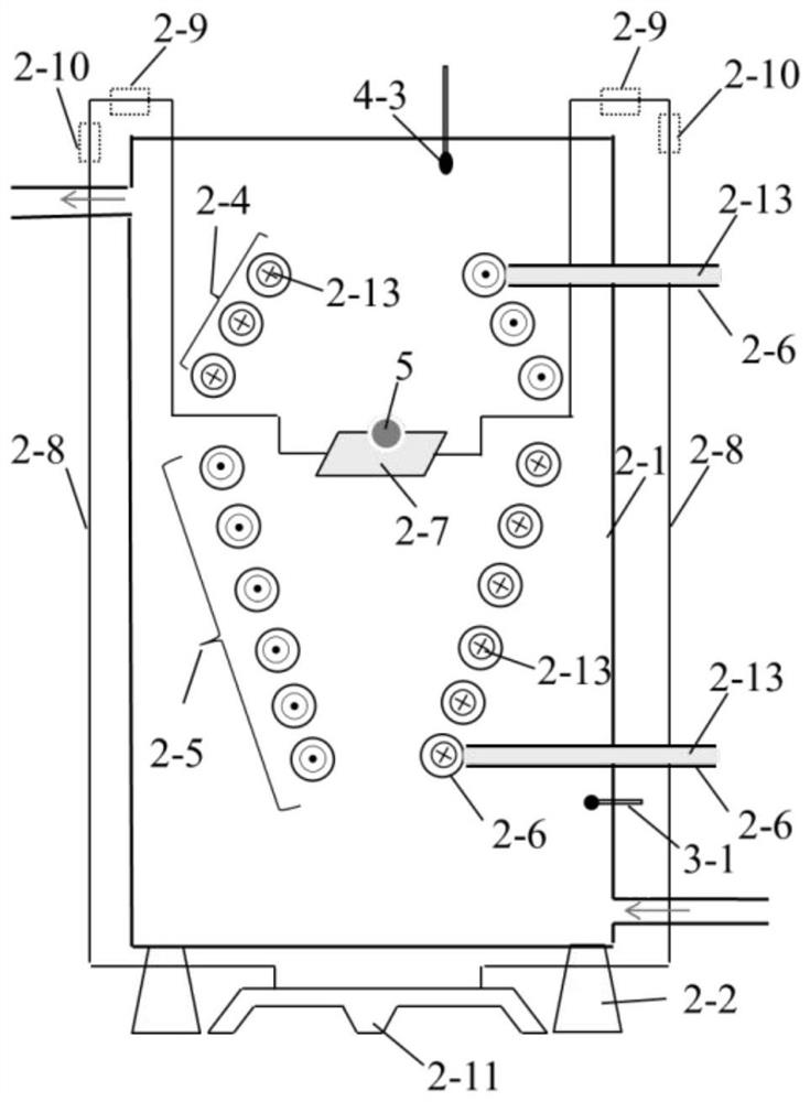
[0031] Refer to attached Figure 1-5 , the suspension-type test equipment for evaluating the uniform corrosion of metal materials in this embodiment is composed of the following systems and devices: data control system 1, suspension system 2, temperature control system 3 and circulation system 4.

[0032] Wherein, the suspension system 2 includes a ceramic chamber 2-1, a chamber support 2-2 for supporting the chamber 2-1, an intermediate frequency AC power supply 2-3, a coil and a weighing device. Wherein the coil includes a stable coil 2-4 and a suspension coil 2-5, and the coil is a copper wire 2-13 wrapped with a coil insulating layer 2-6; the weighing device includes an electronic balance 2-11, a support 2-8, and is arranged on the support The horizontal telescopic knob 2-9 on the 2-8 and the vertical telescopic knob 2-10 and the horizontal tray 2-7.

[0033] Specifically, in this em...

Embodiment 2

[0041] Embodiment 2 test method

[0042] The test method of the present embodiment is based on the test equipment in embodiment 1, specifically comprises the following steps:

[0043] 1) Prepare the sample 5 to be tested, and place the sample 5 to be tested on the tray 2-7.

[0044] 2) Adjust the bracket, adjust the horizontal telescopic knob 2-9 and the vertical telescopic knob 2-10 so that the sample 5 to be tested is located in the middle position between the suspension coil 2-5 and the stable coil 2-4, which is convenient for subsequent stable suspended.

[0045] 3) The electronic balance 2-11 sends the weight data applied to the pallet 2-7 by the sample 5 to be tested to the control system 1, and the control system 1 adjusts the size of the power supply 2-3 according to the received weight data to control the sample to be tested. 5 is gradually separated from the tray 2-7, and the test sample 5 is finally suspended between the suspension coil 2-5 and the stabilization c...


PUM


Abstract

The invention discloses test equipment for evaluating uniform corrosion of a metal material, which comprises a suspension system and a control system, wherein the suspension system comprises a coil and a power supply for supplying power to the coil, the control system is used for controlling and adjusting the power supply, and the coil is used for suspending a sample to be tested after being electrified. The test equipment for evaluating the uniform corrosion of the metal material is reasonable in structural design, and the coil is electrified to generate upward magnetic force, so that the to-be-tested sample can overcome gravity to suspend. The frequency of the power supply is adjusted through the control device, and the magnitude of the magnetic force generated by the coil is controlled,so that the to-be-tested sample can suspend stably, unnecessary non-uniform corrosion caused by contact of the metal material in the soaking process is completely avoided, and the accuracy and scientificity of evaluation of the uniform corrosion performance of the material are improved.

Description

technical field [0001] The invention belongs to the technical field of metal material detection, and in particular relates to a test equipment for evaluating uniform corrosion of metal materials and a test method for uniform corrosion of metal materials using the test equipment. Background technique [0002] Corrosion refers to the physical-chemical interaction between the metal and the environment, resulting in changes in the properties of the metal, and often leads to damage to the function of the metal, the environment or the technical system composed of them. In industrial production, there are often problems such as failure of equipment and components due to corrosion of metal materials, which poses a serious threat to production safety. Metal corrosion is generally divided into uniform corrosion and localized corrosion. Among them, uniform corrosion is the most common form of corrosion. Evaluating the uniform corrosion resistance of materials has important guiding sign...

Claims


Application Information

Patent Timeline
IPC IPC(8): G01N17/00
CPCG01N17/006
Inventor 吴祥锋武焕春张度宝方可伟李成涛沈剑罗坤杰王力牛邵蕊任戌秋
Owner SUZHOU NUCLEAR POWER RES INST
Why Eureka
Try Eureka