
Adjustable wall formwork device and construction method

A construction method and an adjustable technology, which can be applied in the direction of formwork/formwork/work frame, connectors of formwork/formwork/work frame, and on-site preparation of building components, which can solve the waste of materials, the influence of manual installation errors, etc. problems, to achieve the effect of reliable connection, strong applicability, guarantee of flatness and linearity

Pending Publication Date: 2021-03-09
SHANGHAI CONSTR NO 5 GRP CO LTD
View PDF0 Cites 0 Cited by
  • Summary
  • Abstract
  • Description
  • Claims
  • Application Information

AI Technical Summary

Problems solved by technology

[0007] The purpose of the present invention is to provide an adjustable wall formwork device and construction method, which is used to solve the problem that traditional formwork wastes materials and is greatly affected by manual installation errors

Method used


Image

  • Adjustable wall formwork device and construction method

Examples


Embodiment 1

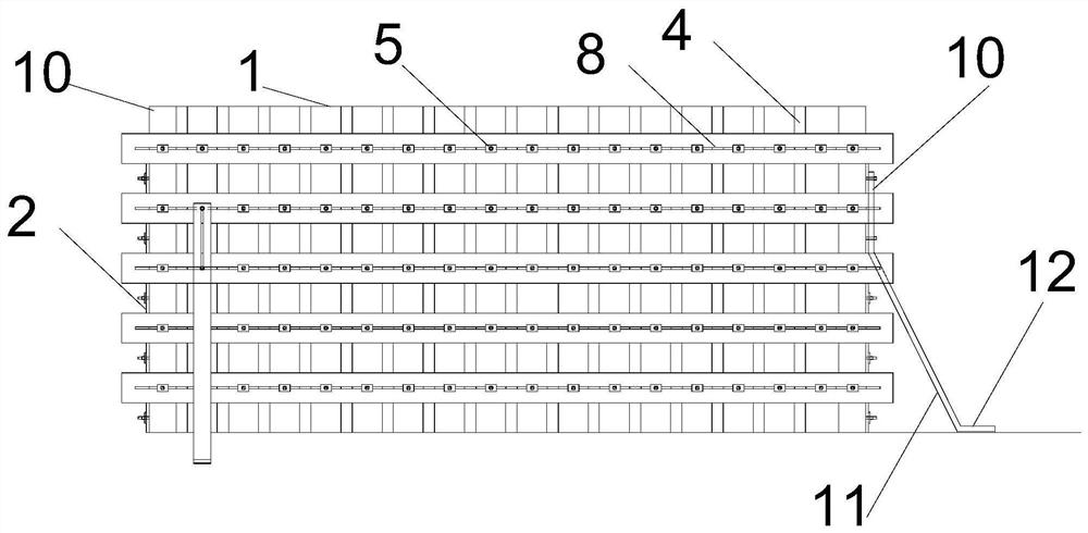
[0034] Such as figure 1 As shown, an adjustable wall formwork device includes bamboo plywood 1, right-angle steel slats 2, vertical corrugations 4, horizontal corrugations and steel diagonal braces, bamboo plywood 1 is spliced ​​into a rectangular outline of the outer wall; right-angle steel slats 2 The right-angled surface is provided with staggered rebars, and the four right-angled sides of the right-angled steel strips 2 are attached to the bamboo plywood 1; The positions of the rebars are horizontally aligned, and the positions of the vertically corrugated rebars 5 on adjacent two surfaces are staggered; grooves are provided on the horizontal corrugations, and the width of the horizontal corrugated grooves is consistent with the diameter of the vertical corrugated rebars 5. The vertical corrugated rebar 5 is set through the grooves and fixed by steel plates with holes and nuts; the steel braces include the upper section 11, the middle section 12 and the lower section 12 wh...

Embodiment 2

[0040] Please continue to refer figure 1 , the present invention also provides a construction method for an adjustable wall formwork, the construction method comprising the following steps:

[0041] Step S1, laying out wires on the ground to locate the outer edge of the cast-in-place wall, placing the pre-enclosed columnar bamboo plywood 1 at the location, and attaching the right-angled steel strips 2 with staggered rebars to the sides of the bamboo plywood 1 The four right-angled sides are fixed;

[0042] Step S2, horizontal flutes and vertical flutes 4 are arranged at intervals respectively on the outside of the bamboo plywood 1, grooves are provided on the horizontal flutes, and rebars are provided on the vertical flutes, the diameter of the rebars is consistent with the width of the grooves, and the grooves on the same horizontal line The vertical corrugated rebar 5 is set through the groove, and after being adjusted to a suitable distance, it is fixed by a steel plate wi...


PUM


Abstract

The invention relates to an adjustable wall formwork device and a construction method, and belongs to the technical field of building construction. The adjustable wall formwork device and the construction method are used for solving the problem that a traditional formwork is large in limitation. According to the adjustable wall formwork device, a steel frame structure formed by right-angle steel plate strips, vertical edges, transverse edges and steel inclined struts is arranged on the periphery of a wall rectangular outline spliced by bamboo plywood; the right-angle steel plate strips with deformed steel bars are attached to the four right-angle edges of the bamboo plywood; the vertical edges and the transverse edges are arranged in a staggered mode at intervals; the transverse edges andthe vertical edges are fixed through groove strips arranged on the transverse edges and are locked through steel plates with holes and nuts; and the steel inclined struts are in a three-section combined type, the three sections are connected in a hinged mode, the whole structure is convenient to assemble and firm in connection, and the influence of manual installation errors is small. Compared with the traditional formwork, the adjustable wall formwork device is higher in stability and can be repeatedly used in a turnover mode, multiple sets of formworks are replaced, the manufacturing numberof the formworks is decreased, the mass is small, the precision is high, and the flatness and the line shape of the pouring quality of a concrete structure are guaranteed.

Description

technical field [0001] The invention relates to the technical field of building construction, in particular to an adjustable wall formwork device and a construction method. Background technique [0002] At present, in domestic building construction, the commonly used wooden formwork forms for cast-in-place walls are mainly divided into the following two types: one is the steel frame structure formwork system, which has relatively large limitations, and the surrounding frames have fixed the length and height of the wall. Only the width of the wall can be adjusted, which greatly reduces the applicability. For walls of different sizes, the formwork needs to be remade, which costs a lot. [0003] The other is the all-steel formwork. This structure is beneficial to control the linearity of the wall during pouring, but the amount of scrap steel is too much, and in many cases it is unnecessary to use a full-section enclosure. [0004] The aforementioned two forms of formwork have ...

Claims


Application Information

Patent Timeline
Patent Type & Authority Applications(China)
IPC IPC(8): E04G11/06E04G11/12E04G17/00E04G17/14
CPCE04G11/06E04G11/12E04G17/001E04G17/14
Inventor 杨俊刘星高腾贾宇倩
Owner SHANGHAI CONSTR NO 5 GRP CO LTD
Learn More