
A Method for Machining Stepped Hole from Small Hole End

A stepped hole and hole end technology, applied in boring/drilling, metal processing equipment, drilling/drilling equipment, etc., can solve the problems of impacting the tool holder, difficult to ensure coaxiality, and inability to process, and achieves guaranteed Dimensional accuracy and machining depth, avoiding tool holder breakage, and ensuring the effect of coaxiality

Active Publication Date: 2022-04-08
SHENYANG BLOWER WORKS GRP NUCLEAR PUMP
View PDF0 Cites 0 Cited by
  • Summary
  • Abstract
  • Description
  • Claims
  • Application Information

AI Technical Summary

Problems solved by technology

However, because the reverse countersinking tool can only realize the machining of countersinking holes with a depth of less than 3mm, if the depth of the stepped hole is greater than 5mm, it is often easy to cause the tool holder or blade to break due to poor chip removal, and the machining cannot be completed well.
Moreover, when machining the stepped hole in the reverse direction, there is a relatively large gap between the tool body and the small hole in order to facilitate the advance / retraction of the reverse countersink. Even so, after the reverse countersink is processed to the bottom of the stepped hole, it will At the intersection of the small aperture and the large aperture, a high point of chip accumulation is formed. When the tool exits the small hole, it will hit the tool holder and cause it to break
At the same time, under the action of the cutting force, the cutter body swings along the circumferential direction of the inner wall of the small hole. Due to the uncontrollable amplitude of the swing, the diameter of the processed stepped hole changes irregularly, resulting in poor roundness of the stepped hole, which cannot meet the requirements. At the same time, it is difficult to ensure the coaxiality between the stepped holes and the small holes after processing

Method used


Image

  • A Method for Machining Stepped Hole from Small Hole End
  • A Method for Machining Stepped Hole from Small Hole End
  • A Method for Machining Stepped Hole from Small Hole End

Examples


Embodiment Construction

[0046] A method for processing a stepped hole from a small hole end provided by an embodiment of the present invention includes the following steps:

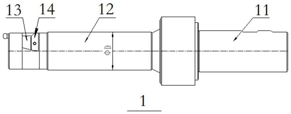
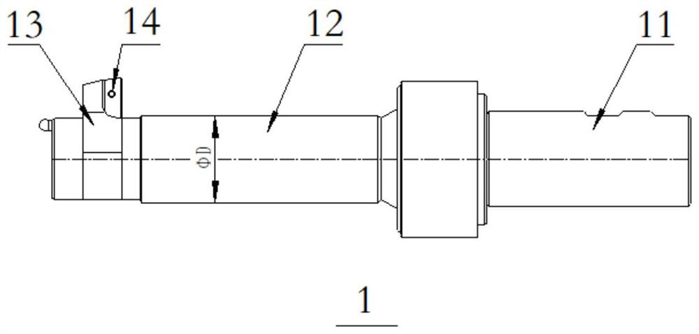
[0047] 1) Parts clamping and tooling: Align the parts and fix them on the console, so that the small diameter end of the stepped hole to be processed on the part faces the direction of the main shaft of the processing equipment, and the centerline of the small diameter of the stepped hole is aligned with the equipment The axis of the spindle. When machining the small hole of the stepped hole, the drill bit and the boring tool (or reamer) are respectively clamped on the equipment spindle, and the reverse countersink is clamped on the equipment spindle when machining the stepped hole with a larger diameter on the other side of the stepped hole . see figure 2 and image 3 , the reverse spot facing tool 1 includes a handle 11 , a tool body 12 , a tool holder 13 and a blade 14 . Wherein, one end of the handle 11 is connected wit...


PUM


Abstract

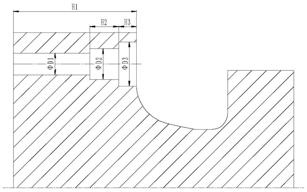
The invention provides a method for machining a stepped hole from a small hole end. The steps include: aligning and clamping the part, clamping a drill bit on the main shaft of the processing equipment, and machining a through hole φD1 with a minimum diameter of H1 and a diameter of φD1 on the part. ;Machining the first stepped hole with diameter φD3 and hole depth H3 at the end of the smallest diameter through hole φD1 far away from the end of the main shaft of the equipment; Second stepped hole. The invention provides a method for machining stepped holes from the small hole end, which can not only ensure that the holes in the processed stepped holes have higher coaxiality, higher dimensional accuracy and higher processing depth, but also can It can effectively avoid the breakage of the tool holder caused by accumulated chips hitting the tool holder when the reverse countersink exits the small hole.

Description

technical field [0001] The invention relates to the technical field of step hole processing, in particular to a method for processing a step hole from a small hole end. Background technique [0002] see figure 1 , the joint holes of some precision parts are stepped holes, the aperture size of each stepped hole is φD3>φD2>φD1, and the hole depth of each stepped hole is H1>H2>H3. When machining stepped holes, the requirements for the coaxiality between each stepped hole, the surface quality of each stepped hole and the accuracy of dimensional tolerance are relatively high. Moreover, for some parts where the stepped hole is located, it is often not allowed to process from the large aperture end, and the stepped hole can only be reversely processed from the small aperture end. [0003] The conventional method of reverse machining a stepped hole is to use a reverse countersink to reverse process the large hole at the other end from the small diameter end. However, bec...

Claims


Application Information

Patent Timeline
Patent Type & Authority Patents(China)
IPC IPC(8): B23B35/00B23B41/00
CPCB23B41/00B23B35/00
Inventor 刘文英王芳孟艳玲关锰王学宇田云李晖王良贾洪岩胡英俊袁林牟思宇
Owner SHENYANG BLOWER WORKS GRP NUCLEAR PUMP
Learn More