
Manufacturing method of sliding part, sliding part and textile machine using same

A manufacturing method and technology for sliding parts, which are applied to mechanical equipment, processing of textile materials, rotating parts resistant to centrifugal force, etc., can solve problems such as the influence of powder metallurgy process implementation procedures, increase separate procedures, etc., so as to reduce the risk of combined failure and resistance. The effect of broken extension path and qualified mechanical properties

Active Publication Date: 2021-12-24
SANYANG TEXTILE
View PDF20 Cites 0 Cited by
  • Summary
  • Abstract
  • Description
  • Claims
  • Application Information

AI Technical Summary

Problems solved by technology

This pretreatment of the material interface at present often has a great impact on the implementation procedures of the powder metallurgy process, such as having to press the powder separately or having to add a separate program for the treatment of the interface

Method used


Image

  • Manufacturing method of sliding part, sliding part and textile machine using same
  • Manufacturing method of sliding part, sliding part and textile machine using same
  • Manufacturing method of sliding part, sliding part and textile machine using same

Examples


Embodiment 1

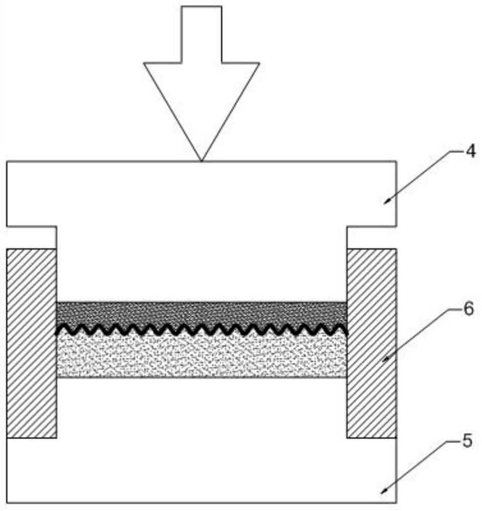
[0030] see first image 3 , in this example image 3 In the hot pressing die shown, the powder metallurgy method is used to make a bi-material or multi-material planar slide, which is used as a sliding bearing in textile machinery. The hot pressing mold structure includes an upper template 4, a lower template 5 and a mold cover 6, and the upper template 4, the lower template 5 and the mold cover 6 encircle the powder raw material feeding cavity and the molding cavity of the slider.

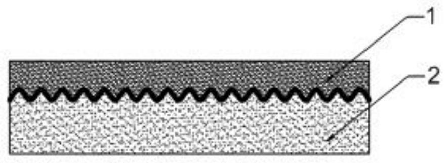
[0031] combine Figure 1-Figure 3 , the method for making the slider includes: using the second powder material 2 as the powder raw material for the supporting material layer, using the first powder material 1 as the raw material for the working material layer, laying materials in order, and using the second powder material as the powder raw material for the supporting material layer 2 on the bottom, the first powder material 1 as the raw material of the working material layer is on the top, and...

Embodiment 2

[0038] see still Figure 1-Figure 4 , the preparation target, the hot pressing mold used and the process adopted in this embodiment are basically the same as those in Example 1, and the interface structure template 3 adopted is also the same, the difference is that in the sequential laying of materials, The laid second powder material 2 and the first powder material 1 are both mixed with a binder with a volume content of 8%, and the second powder material 2, the interface construction template 3, and the first powder material 1 are laid in sequence. After that, degreasing and sintering are carried out. During the degreasing process, the interface structure template 3 is decomposed and removed together with the binder.

[0039] The final temperature of the above-mentioned degreasing process in this embodiment is based on the fact that the adhesive and the interface structure template 3 can be completely decomposed, and the processes of pressurization, degreasing and sintering i...


PUM

PropertyMeasurementUnit
thicknessaaaaaaaaaa
thicknessaaaaaaaaaa

Abstract

The manufacturing method of the sliding part adopts the powder metallurgy method to make a two-material or multi-material planar sliding part, such as a sliding bearing of a textile machine, using the second powder material as the powder raw material of the supporting material layer, and using the first powder material as the raw material of the working material layer, Lay materials in order, the second powder material is on the bottom, the first powder material is on the top, and a thin plate with an undulating structure and made of thermally decomposable materials is placed between the second and first powder materials as an interface construction template, which can Remove between the second and first powder materials by degassing, pre-firing or degreasing, and after removing the interface construction template, the second and first powder materials are respectively metallurgically sintered to form a support material layer and a working material layer. A non-linear interface structure corresponding to the undulating structure shape of the interface structure template is formed at the sintering interface of the material layer and the working material layer. The method does not require separate pressing of the powders, and does not add a separate operating procedure to treat the interface.

Description

technical field [0001] The invention relates to the technical field of manufacturing mechanical sliding parts, in particular to a method for manufacturing a sliding part, a sliding part and a textile machine using the sliding part. Background technique [0002] Planar sliding parts such as sliding bearings are parts used to withstand sliding friction in mechanical equipment, and can adapt to low-speed and heavy-load working conditions. Bearings are widely used as friction pairs in textile machinery because they avoid the use of lubricating oil. [0003] Many planar bearings with self-lubricating ability are dual-material or multi-material bearings, which include a support material layer for support and at least one working material layer for friction and lubrication, so they can also be produced by powder metallurgy. In the process, the iron-based powder material is used as the powder raw material of the supporting material layer, and the copper-based powder material with s...

Claims


Application Information

Patent Timeline
Patent Type & Authority Patents(China)
IPC IPC(8): B22F5/00B22F3/14B22F3/10B22F1/00F16C33/12F16C33/14
CPCB22F5/00B22F3/1021B22F3/14F16C33/121F16C33/14F16C2204/60F16C2220/00F16C2340/00B22F1/10
Inventor 张尧宗张官泽
Owner SANYANG TEXTILE
Learn More