Packaging sheet rapid stamping die

A technology for stamping dies and packaging sheets, which is applied in the direction of perforation tools, manufacturing tools, cleaning methods and appliances, etc. It can solve the problems of reducing the accuracy of hole spacing and the decline in the pass rate of stamping products, so as to improve the stamping accuracy and product pass rate Effect

Inactive Publication Date: 2021-03-09
广州迎善信息科技有限公司
View PDF0 Cites 0 Cited by
  • Summary
  • Abstract
  • Description
  • Claims
  • Application Information

AI Technical Summary

Problems solved by technology

[0004] The main purpose of the present invention is to overcome the deficiencies of the prior art, and provide a rapid stamping die for packaging sheets to solve the problem that the central end of the stamping part is impacted up and down by the overall mold panel to form die-casting. The strong interaction between t

Method used


Image

  • Packaging sheet rapid stamping die
  • Packaging sheet rapid stamping die
  • Packaging sheet rapid stamping die

Examples


Embodiment 1

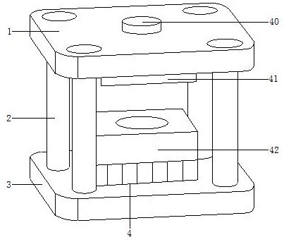
[0024] Example 1 see Figure 1-3 , the present invention provides a technical scheme of rapid stamping die for packaging sheet: its structure includes an upper template 1, a stamping strut 2, a lower template 3, and a stamping mold 4, and the stamping strut 2 is connected to the upper template 1 and the lower template 3 axes connected, the stamping die 4 is installed on the upper template 1 and the lower template 3, the upper template 1 and the lower template 3 have the same structure, and the stamping die 4 is composed of a shaft 40, an upper template 41, a lower template 42, the loading shaft 40 is installed and connected with the upper formwork 41 and the lower formwork 42, the upper formwork 41 is installed on the upper formwork 1, and the upper formwork 1 drives the upper formwork 41 on the stamping pole 2 Lifting and flexible transmission, the lower formwork 42 is installed on the lower formwork 3, the upper formwork 41 has the same structure as the lower formwork 42, an...

Embodiment 2

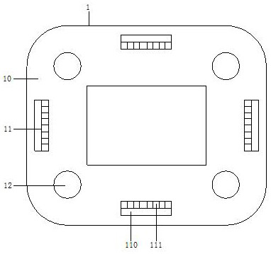
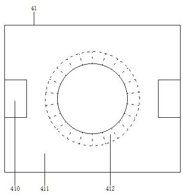
[0026] Example 2 see Figure 4 , 5 , the present invention provides a technical solution for a rapid stamping die for packaging sheets: the internal dust collection structure 410 includes a rotating dust collector 4100, a structural block 4101, a lateral moving dust collector 4102, and a structural rail 4103. The dust collector 4100 is used for dust collection of metal shavings between the mold and the plate, the traverse dust collector 4102 is used for collecting the metal shavings when opening holes, the structural block 4101 and the rotary dust collector 4100, traverse The dust collector 4102 is installed and connected, the dust collector 4102 is locked with the structural rail 4103, the plate body 411 is equipped with a lifting vertical rail 4110, and the plate hole 412 includes a connecting hole ring 4120 and a hole fan structure 4121, the connection hole ring 4120 is installed and connected with the hole fan structure 4121, the hole fan structure 4121 is installed with ...


PUM


Abstract

The invention discloses a packaging sheet rapid stamping die which structurally comprises an upper die plate, stamping supporting rods, a lower die plate and a stamping section die. The stamping supporting rods are connected with the upper die plate and the lower die plate through shafts, the stamping section die is installed on the upper die plate and the lower die plate, the upper die plate andthe lower die plate are same in structure, and the stamping section die comprises a mounting shaft, an upper section die plate and a lower section die plate. The mounting shaft is connected with the upper section die plate and the lower section die plate in a mounted mode, the upper section die plate is installed on the upper die plate, the lower section die plate is installed on the lower die plate, and the upper section die plate and the lower section die plate are same in structure. According to the packaging sheet rapid stamping die, dust collectors are of a concealable structure and are used for collecting metal dust in a large range, a large number of metal chips which are generated between the die and a plate in the plate machining process are collected through rotary dust collectors, the metal chips at the stamping hole position are collected through transverse moving dust collectors, the stamping precision is improved, and the product percent of pass is increased.

Description

technical field [0001] The invention relates to the field of molds, in particular to a rapid stamping mold for packaging sheets. Background technique [0002] The stamping strips on the high-efficiency automatic stamping die are automatically fed for stamping, that is, the conveying step size is controlled by a special feeding mechanism. If the feeding mechanism has high precision in the conveying step size, the dimensional accuracy of the stamped products is also high. high. [0003] In the prior art, the central end of the stamping part is impacted up and down by the overall mold panel to form a die-casting process, and the strong interaction between the stamping die and the plate during the die-casting process will generate a large amount of metal chips during the processing of the plate. When the hole is opened, the metal shavings will enter the hole together, which will reduce the accuracy of the hole distance, and the hole will form a chip groove, that is, the pass ra...

Claims


Application Information

Patent Timeline
IPC IPC(8): B21D28/34B08B5/04
CPCB08B5/04B21D28/34
Inventor 林建玲
Owner 广州迎善信息科技有限公司
Why Eureka
Try Eureka