Laser welding process for welding nickel-plated copper with thickness of 200 microns by employing single-mode laser

A laser welding and laser welding technology, applied in laser welding equipment, welding equipment, manufacturing tools, etc., to achieve the effect of ensuring quality, good weld formation, and improving process environment

Pending Publication Date: 2021-03-05
SHANGHAI SKEQI AUTOMATION ENG CO LTD
View PDF5 Cites 5 Cited by
  • Summary
  • Abstract
  • Description
  • Claims
  • Application Information

AI Technical Summary

Problems solved by technology

[0005] The purpose of the present invention is to provide a laser welding process for welding 200 micron thick nickel-plated copper with a single-mode laser. The present invention adopts the laser welding process, adjusts various welding process parameters and improves the process environment in the welding process to ensure that the weld seam is formed Good, no macroscopic defects, all aspects of performance meet the production and application standards, solve the welding problem when this kind of nickel-plated copper is used in the production of positive electrodes of battery tabs, and ensure the quality of such welded joints

Method used


Image

  • Laser welding process for welding nickel-plated copper with thickness of 200 microns by employing single-mode laser
  • Laser welding process for welding nickel-plated copper with thickness of 200 microns by employing single-mode laser
  • Laser welding process for welding nickel-plated copper with thickness of 200 microns by employing single-mode laser

Examples


Embodiment Construction

[0020] The present invention will be described in detail below in conjunction with the embodiments shown in the accompanying drawings.

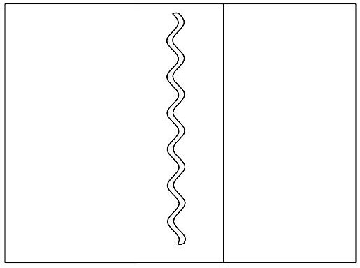
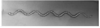
[0021] figure 1 It is a schematic diagram of the overlap of plates of the present invention; figure 2 It is a schematic diagram of welding in the present invention; the welding path in the figure is a hyperbola. image 3 It is the effect diagram of material welding after the material of the embodiment is welded.

[0022] In order to more clearly illustrate the technical solutions in the embodiments of the present invention, the following will briefly introduce the drawings required for the description of the embodiments or prior art, and the drawings in the description are only part of the embodiments of the present invention. For those skilled in the art, other drawings can also be obtained based on these drawings without creative effort.

[0023] In the following description, numerous specific details are given in order to provide a mor...


PUM

PropertyMeasurementUnit
lengthaaaaaaaaaa
thicknessaaaaaaaaaa

Abstract

The invention relates to a laser welding process, and particularly relates to a laser welding process for welding nickel-plated copper with the thickness of 200 microns by employing a single-mode laser. The laser welding process is characterized in that a welding clamp is a copper cup pressing mechanism and presses the periphery of a welding part of a test piece, and shielding gas is blown out inthe welding process to protect the welding part; an experimental material is placed on a workbench, a copper cup is controlled to move to the welding part through a PLC program and is pressed, and anair blowing instruction is given through a PLC in the welding process; the laser is the single-mode laser, a galvanometer head is adopted for welding, the defocusing amount is +2mm, and the laser power, the welding speed and the welding path are adjusted through a laser control system; and employed process parameters of the laser welding are as follows: the laser power is 900w-1200w, the welding speed is 170mm / s-240mm / s, the welding path is a hyperbola, and the defocusing amount is + 2mm. In the welding process, various welding process parameters are adjusted, the process environment is improved, it is guaranteed that welds are well formed, macroscopic defects are avoided, all performances meet the production and application standards, the welding problem generated when the nickel-plated copper is applied to the production of the positive electrode of the battery tab is solved, and the quality of the welding joints is guaranteed.

Description

technical field [0001] The invention relates to a laser welding process, in particular to a laser welding process for welding 200 micron-thick nickel-plated copper with a single-mode laser. Background technique [0002] In the tab welding of new energy lithium batteries, nickel-plated copper, copper, and aluminum are commonly used. These three materials are used as battery tabs for welding. The traditional welding method is ultrasonic welding, but after ultrasonic welding, there will be virtual welding, Defects such as burrs, unstable pulling force, unstable discharge current, and excessive resistance. Ultrasonic welding adopts material contact processing, which puts forward high requirements on the parallelism and flatness of the material surface, which makes it impossible to process stably. Therefore, in recent years, many manufacturers use laser welding technology instead of ultrasonic welding. [0003] Laser welding has the advantages of high energy density, fast weldi...

Claims


Application Information

Patent Timeline
Patent Type & Authority Applications(China)
IPC IPC(8): B23K26/21B23K26/12B23K26/60B23K26/70B23K26/06
CPCB23K26/21B23K26/123B23K26/60B23K26/70B23K26/0626
Inventor 叶海青许广伟毛欢庆
Owner SHANGHAI SKEQI AUTOMATION ENG CO LTD
Why Eureka
Try Eureka